Silicon Controlled Switch (SCS) – Symbol, Operation, Advantages and Application:
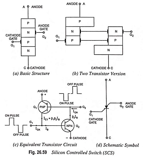
Silicon controlled switch (SCS), like the SCR, is a unilateral, four layer, three junction P-N-P-N silicon device with four electrodes namely cathode C, cathode gate G1, anode gate G2 and the anode A, as shown in Fig. 26.59.
Infact, the Silicon Controlled Switch is a low power device compared with the SCR. It handles currents in milliamperes rather than amperes. SCS differs from an SCR in the following aspects :
- It has an additional gate—the anode gate.
- It is physically smaller than SCR.
- It has smaller leakage and holding currents than SCR.
- It needs small triggering signals.
- It gives more uniform triggering characteristics from sample to sample.
The basic structure and schematic symbol of Silicon Controlled Switch (SCS) are shown in Figs. 26.59 (a) and 26.59 (d) respectively. It may be fabricated by using either the grown junction technique or the planar technique.
Operation of Silicon Controlled Switch:
The easiest way to understand how it operates is to realize it to be formed of two transistors Q1 and Q2 placed back-to-back, as shown in Fig. 26.59 (b).
In a two-transistor equivalent circuit shown in Fig. 26.59 (c), it is seen that a negative pulse at the anode gate G2 causes transistor Q1 to switch on. Transistor Q1 supplies base current to transistor Q2, and both transistors switch on. Similarly, a positive pulse at the cathode gate G1 can switch the device on. Since only small currents are involved, the SCS may be switched off by an appropriate polarity pulse at one of the gates. At the cathode gate a negative pulse is required for switching off while at the anode gate a positive pulse is needed.
Volt-Ampere Characteristic:
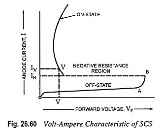
The volt-ampere characteristic of an Silicon Controlled Switch is similar to that of an SCR and is shown in Fig. 26.60. With the increase in applied voltage, the current first increases slowly upto point A and then rapidly in the region AB, as shown in the figure. At point B, the product β1β2 exceeds unity and the device is suddenly switched on. In the on-state, the current increases enormously and is limited by the external series resistor. SCS also exhibits negative differential resistance in the on region similar to SCR. SCS gets switched on accidentally if the anode voltage gets applied suddenly. This is known as rate effect, which is caused by interelectrode capacitance between electrodes G1 and G2 known as transition capacitance.
Advantages:
An advantage of SCS over an SCR is the reduced turn-off time, typically within the range of 1 to 10 μs for the SCS and 5 to 30 μs for the SCR. Other advantages of the SCS over SCR are increased control and triggering sensitivity and a more predictable firing situation. However, the SCS is limited to low power, current, and voltage ratings (typical maximum anode currents range from 100 mA to 300 mA with dissipation rating of 100 to 500 mW).
Applications:
A few of the more common areas of application of Silicon Controlled Switch include a variety of computer circuits (such as counters, registers, and timing circuits) voltage sensors, pulse generators, oscillators etc.