Peak to Peak Detector – Working Principle and Applications:
A half-wave rectifier with a capacitor-input filter provides a dc output voltage roughly equal to the peak of the input signal. The same circuit with a small-signal diode is known as a peak detector. Typically, peak detectors operate at frequencies that are much higher than 50 Hz. The output of a peak detector is used in measurements, signal processing, and communications.
Peak-to-peak detector can be had simply by cascading a dc clamper and a peak detector. The input sine wave is positively clamped, so the input to peak detector has a value of 2VP. That is why the output of peak detector is a dc voltage of magnitude 2VP.
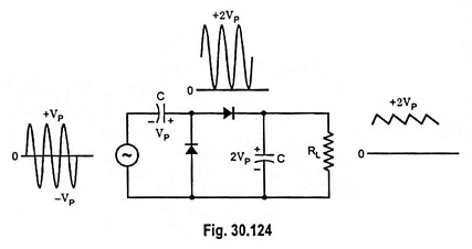
As usual, the discharge time constant RLC must be much greater than the period of the input signal. If this condition is satisfied, good clamping action and good peak detection will be obtained. The output ripple will, therefore, be small.
One application is in measurement of nonsinusoidal signals. An ordinary ac voltmeter (an ac voltmeter calibrated to read rms values) when used to measure nonsinusoidal signal, it will give erroneous indication. However, if the output of a peak-to-peak detector is used as the input to a dc voltmeter, it will indicate the peak-to-peak voltage. If the nonsinusoidal signal under measurement swings from –30 to +55 V, the reading will be 85 V.