Peak Reading Voltmeter Circuit:
Sometimes it is enough if the Peak Reading Voltmeter Circuit of an impulse voltage wave is measured; its waveshape might already be known or fixed by the source itself. This is highly useful in routine impulse testing work. The methods are similar to those employed for a.c. voltage crest value measurements.
The instrument is normally connected to the low voltage arms of the potential dividers described in Sec. 7.2.7. The basic circuit along with its equivalent circuit and the response characteristic is shown in Fig. 7.41. The circuit consists of only rectifiers.
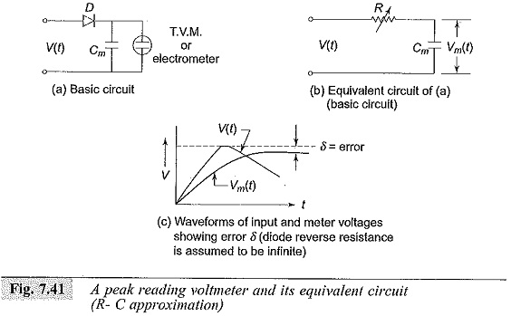
Diode D conducts for positive voltages only. For negative pulses, the diode has to be connected in reverse. When a voltage impulse ν(t) appears across the low voltage arm of the potential divider, the capacitor Cm is charged to the peak value of the pulse. When the amplitude of the signal starts decreasing the diode becomes reverse biased and prevents the discharging of the capacitor Cm.
The voltage developed across Cm is measured by a high impedance voltmeter (an electrostatic voltmeter or an electrometer). As the diode D has finite forward resistance, the voltage to which Cm is charged will be less than the actual peak of the signal, and is modified by the R-C network of the diode resistance and the measuring capacitance Cm. The error is shown in Fig. 7.41c. The error can be estimated if the waveform is known.
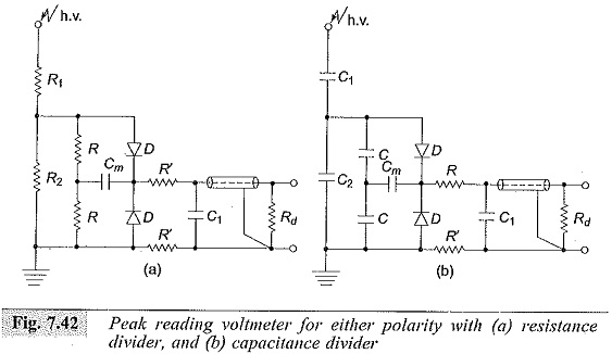
The actual forward resistance of the diode D (dynamic value) is difficult to estimate, and hence the meter is calibrated Using an oscilloscope. Peak voltmeters for either polarity employing resistance dividers and capacitance dividers are shown in Fig. 7.42. In this arrangement, the voltage of either polarity is transferred into a proportional positive measuring signal by a resistive or capacitive voltage divider and a diode circuit.
An active network with feedback circuit is employed in commercial instruments, so that the fast rising pulses can also be measured. Instruments employing capacitor dividers require discharge resistance across the low voltage arm to prevent the build-up of d.c. charge.