Block Diagram of AM Transmitter:
Block Diagram of AM Transmitter is shown in Fig. 22.25.
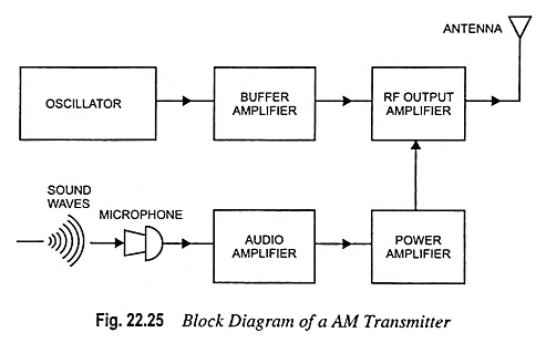
Sound waves produced by speech or music strike the diaphragm of a microphone that converts them into a tiny varying current. The audio frequency output of the microphone is amplified by a low level audio amplifier and, finally, by a power amplifier.
On the other side, the carrier waves of radio frequency are generated by a crystal-controlled oscillator. These carriers waves are applied to a tuned buffer amplifier and finally to an RF output amplifier. Buffer amplifier is used to isolate the RF oscillator and the power amplifier stages.
The amplified audio signal is then combined with the carrier to give a modulated carrier wave which is fed to the transmitter antenna.