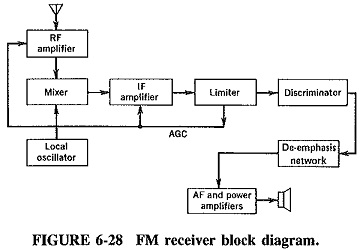
FM Receiver Block Diagram:
The FM receiver is a superheterodyne receiver, and the FM Receiver Block Diagram of Figure 6-28 shows just how similar it is to an AM receiver. The basic differences are as follows:
- Generally much higher operating frequencies in FM
- Need for limiting and de-emphasis in FM
- Totally different methods of demodulation
- Different methods of obtaining AGC
Common Circuits – Comparison with AM Receivers:
A number of sections of the FM receiver correspond exactly to those of other receivers already discussed. The same criteria apply in the selection of the intermediate frequency, and IF amplifiers are basically similar. A number of concepts have very similar meanings so that only the differences and special applications need be pointed out.
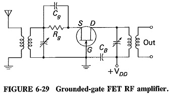
RF amplifiers: An RF amplifier is always used in an FM receiver. Its main purpose is to reduce the noise figure, which could otherwise be a problem because of the large bandwidths needed for FM. It is also required to match the input impedance of the receiver to that of the antenna. To meet the second requirement, grounded gate (or base) or cascode amplifiers are employed. Both types have the property of low input impedance and matching the antenna, while neither requires neutralization. This is because the input electrode is grounded on either type of amplifier, effectively isolating input from output.
A typical FET grounded-gate RF amplifier is shown in Figure 6-29. It has all the good points mentioned and the added features of low distortion and simple operation.
Oscillators and mixers: The oscillator circuit takes any of the usual forms, with the Colpitts and Clapp predominant, being suited to VHF operation. Tracking is not normally much of a problem in FM broadcast receivers. This is because the tuning frequency range is only 1.25 : 1, much less than in AM broadcasting.
A very satisfactory arrangement for the front end of an FM receiver consists of FETs for the RF amplifier and mixer, and a bipolar transistor oscillator. As implied by this statement, separately excited oscillators are normally used, with an arrangement as shown in Figure 6-6.
Intermediate frequency and IF amplifiers:
Again, the types and operation do not differ much from their AM counterparts. It is worth noting, however, that the intermediate frequency and the bandwidth required are far higher than in AM broadcast receivers. Typical figures for receivers operating in the 88- to 108-MHz band are an IF of 10.7 MHz and a bandwidth of 200 kHz. As a consequence of the large bandwidth, gain per stage may be low. Two IF amplifier stages are often provided, in which case the shrinkage of bandwidth as stages are cascaded must be taken into account.