Hartley Oscillator using Transistor Analysis:
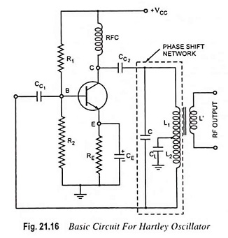
The transistor Hartley oscillator is as popular as Colpitt’s oscillator and is widely used as a local oscillator in radio receivers. The circuit arrangement is shown in Fig. 21.16. Hartley oscillator circuit is similar to Colpitt’s oscillator circuit, except that phase shift network consists of two inductors L1 and L2 and a capacitor C instead of two capacitors and one inductor. The output of the amplifier is applied across inductor L1 and the voltage across inductor L2 forms the feedback voltage. The coil L1 is inductively coupled to coil L2, the combination functions as an auto-transformer. However, because of direct connection, the junction of L1 and L2 cannot be directly grounded. Instead, another capacitor CL is used. The operation of the circuit is similar to that of the Colpitt’s oscillator circuit.
Considering the fact that there exists mutual inductance between coils L1 and L2 because the coils are wound on the same core, their net effective inductance is increased by mutual inductance M. So in this case effective inductance is given by the equation
![]()
and resonant or oscillation frequency is given by the equation
![]()
Frequency of Oscillation:
The general Eq. (21.10) derived in Art. 21.7 is reproduced here
![]()
Here Z1 = jωL1 + jωM; Z2 = jωL2 + jωM and
![]()
Substituting these values in general Eq. (21.10), we get
![]()
Equating the imaginary part of above Eq. (21.28) to zero, we have
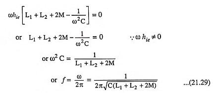
The above Eq. (21.29) gives the frequency of oscillation. Equating the real component of Eq. (21.28) to zero, we get
![]()
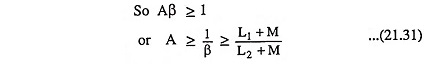
As for other oscillator circuits, the loop gain must be greater than 1 to ensure that circuit oscillates.
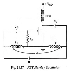
FET Hartley Oscillator:
An FET Hartley oscillator circuit is shown in Fig. 21.17. The noteworthy point is that inductors L1 and L2 have a mutual coupling M, which is to be taken into account in determination of the equivalent inductance for the resonant circuit. This circuit operates at a frequency given by Eq. (21.29).