Colpitts Oscillator using Transistor Circuit:
The Colpitts oscillator circuit is a superb circuit and is widely used in commercial signal generators up to 100 MHz. The basic Colpitts Oscillator using Transistor circuit is shown in Fie. 21.13(a).
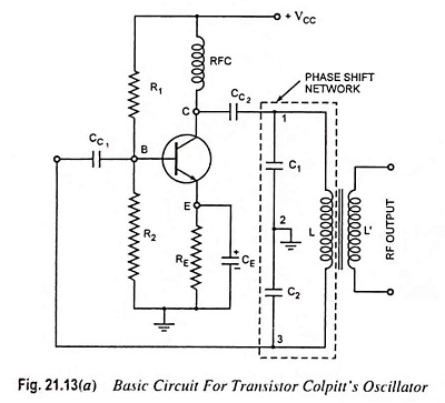
It basically consists of a single stage inverting amplifier and an L-C phase shift network, as obvious from the circuit diagram shown. The two series capacitors C1 and C2 form the potential divider used for providing the feedback voltage—the voltage developed across capacitor C2 provides the regenerative feedback required for sustained oscillations.
Parallel combination of RE and CE along with resistors R1 and R2 provides the stabilized self bias. The collector supply voltage VCC is applied to the collector through a radio frequency choke (RFC) which permits an easy flow of direct current but at the same time it offers very high impedance to the high frequency currents.
The presence of coupling capacitor CC2 in the output circuit does not permit the dc currents to go to the tank circuit (the flow of dc current in a tank circuit reduces its Q). The radio frequency energy developed across RFC is capacitively coupled to the tank circuit through the capacitor CC2.
The output of the phase shift L-C network is coupled from the junction of L and C2 to the amplifier input at base through coupling capacitor CC1, which blocks dc but provides path to ac. Transistor itself produces a phase shift of 180° and another phase shift of 180° is provided by the capacitive feedback. Thus a total phase shift of 360° is obtained which is an essential condition for developing oscillations.
The output voltage is derived from a secondary winding L’ coupled to the inductance L. The frequency is determined by the tank circuit and is varied by gang-tuning the two capacitors C1 and C2. It is to be noted that capacitors C1 and C2 are ganged. As the tuning is varied, values of both capacitors vary simultaneously, the ratio of the two capacitances remaining the same.
Working Principle:
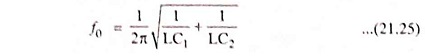
When the collector supply voltage VCC is switched on, the capacitors C1 and C2 are charged. These capacitors C1 and C2 discharge through the coil L, setting up oscillations of frequency
![]()
The oscillations across capacitor C2 are applied to the base-emitter junction and appear in the amplified form in the collector circuit. Of course, the amplified output in the collector circuit is of the same frequency as that of the oscillatory circuit. This amplified output in the collector circuit is supplied to the tank circuit in order to meet the losses. Thus the tank circuit is getting energy continuously from the collector circuit to make up for the losses occurring in it and, therefore, ensures undamped oscillations. The energy supplied to the tank circuit is of correct phase, as already explained, and if Aβ exceeds unity, oscillations are sustained in the circuit.
Frequency of Oscillation:
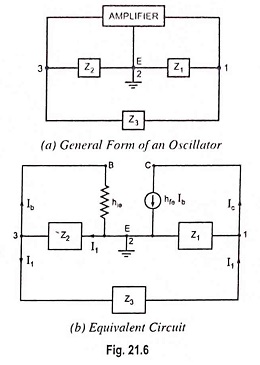
Here referring to Fig. 21.6
![]()
Substituting these values in Eq. (21.10), we have
![]()
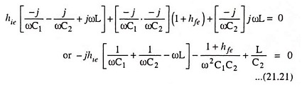
Equating the imaginary component of the above Eq. (21.21) to zero, we have
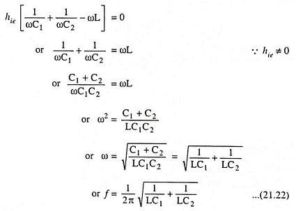
The above Eq. (21.22) provides the frequency of oscillation. Equating the real component of Eq. (21.21) to zero, we have
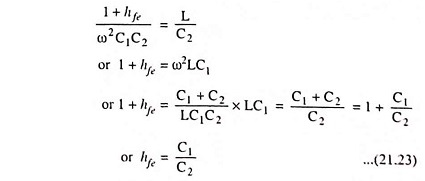
As for other oscillator circuits, the loop gain must be greater than unity to ensure that the circuit oscillates.
So
![]()
FET Colpitts Oscillator:
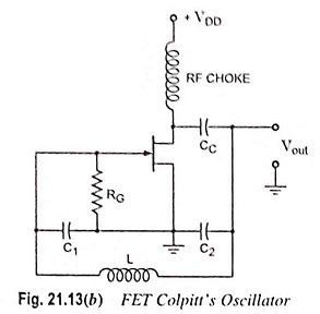
A practical version of an FET Colpitts oscillator is shown in Fig. 21.13(b). Here, RG is the gate biasing resistor. The RFC choke performs two functions. (i) It keeps ac current out of the dc drain supply and (ii) it provides drain load. As seen, C1 is in the input circuit whereas C2 is in the output circuit. The oscillator frequency can he determined by the same relation as in case of transistor Colpitts oscillator i.e. by relation