Current to Voltage Converter Circuit:
A device that produces a voltage proportional to input signal current is called a Current to Voltage Converter Circuit. The circuit arrangement is shown in Fig. 36.27.
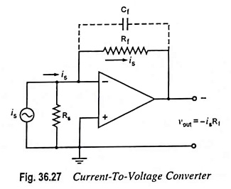
In this circuit, a photocell or photomultiplier tube that provides output current proportional to the light flux but independent of the load impedance, is connected to the inverting input terminal of the op-amp. Rs is the shunt source resistance. As there is a virtual ground at the inverting input terminal, current flowing through Rs is zero and, therefore, the entire input current is flows through the feedback resistor Rf resulting in the output voltage given as
![]()
The above equation clearly indicates that the output voltage is directly proportional to the input (source) current is.
However, in this circuit, the lower limit on current measurement is set by the bias current of the inverting input. Often a capacitor Cf is connected in parallel with resistor Rf for reducing the high frequency noise and the possibility of oscillations.
Applications:
One of the most common uses of the current-to-voltage converter is in sensing current from photodetectors and in digital-to-analog converter applications.