Clamping Circuit Theorem:
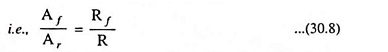
Under steady-state conditions, for any input waveform, the shape of the output waveform of a clamping circuit is fixed and also the area in the forward direction and the area in the reverse direction are related. According to clamping circuit theorem, under steady-state conditions, the ratio of area in forward direction Af to that of reverse direction Ar of output voltage is equal to the ratio of diode forward resistance Rf to resistance R connected across diode.
This theorem applies quite generally independent of the input waveform and the magnitude of the source resistance.
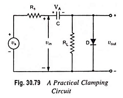
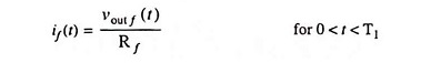
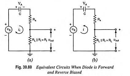
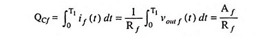
Proof: Consider the clamping circuit shown in Fig. 30.79. Let for first half cycle of input signal diode be on, the equivalent circuit is shown in Fig. 30.80 (a). If vout f(t) is the output waveform in the forward direction, then the capacitor charging current is
Therefore, the charge stored in the capacitor during the forward interval is
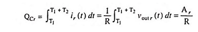
Similarly for interval T1 < t <T1 + T2, the input is low and the diode is off and the equivalent circuit is as shown in Fig. 30.80 (b). If vout r(t) is the output voltage in the reverse direction, then the discharging current of capacitor is

Thus, the charge lost by the capacitor during the reversal interval is
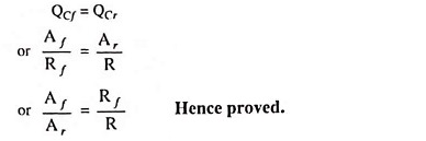
Under steady-state conditions, the net charge gain of the capacitor over one complete cycle must be equal to zero, therefore,