Varistors or Voltage Dependent Resistors (VDRS):
Varistors, also called the voltage dependent resistors (VDRs), show a high degree of nonlinearity between their resistance value and the applied voltage. They are made of non-homogeneous materials giving a rectifying action at the contact of two particles. Various materials, such as silicon carbide, zinc oxide, are used to manufacture VDRs.
The electrical characteristic of the conglomeration is determined by a large number of crystal contacts which form a complicated network of series and parallel rectifying contacts.
These resistors have found a diversity of applications in the different sectors of electronics. They offer a cheap and reliable solution for protection of electronic circuits, semiconductor components, motors, relay contacts, etc. against overvoltages and their consequences.
Manufacturing Process:
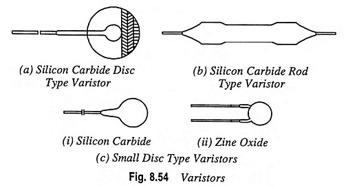
Crystals of silicon carbide, or of metal oxides, with the right electrical and dimensional properties are pressed together with a ceramic binder to the shape of discs or rods (Fig. 8.54). After a drying period the varistors are sintered at a high temperature. Firing time, temperature and gaseous atmosphere have an important influence on the electrical characteristics. The contacts are metallized with silver or copper enabling good electrical contact. After leads have been soldered to the contacts the varistors are lacquered and coded. Some types, made for clamp contacts or other mounting methods, are delivered unlacquered and without loads.
Electrical Properties:
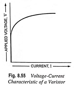
The relation between voltage and current of a varistor can be approximated by equation
![]()
where V is the applied voltage in volts, I the current in amperes and C and β are constants. This equation is illustrated in Fig. 8.55.
The varistors do not have a polar effect; this means that when the voltage is changed from positive to negative, the current changes its direction, but retains its value. For practical design, reference is made to the V-I characteristic given in the data sheets of the relevant varistor types.
The C and β values of varistors depend on the composition of the material and on the method used in the processing; furthermore, the value of C depends on the shape and dimensions of the varistor. Practical value of β for SiC are 0.15 to 0.40 and for ZnO are 0.02 to 0.035.
Note: On no occasion may a varistor be connected in parallel with the aim of obtaining the higher power dissipation.
Resistance Value: When defining R as usual as the quotient of voltage and current we find
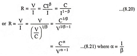
From these equations it is once more evident that the resistance value is not a constant one, but is very much dependent on the values of V and I.
Dissipated Power: The power dissipated in a varistor is equal to the product of voltage and current, so it may be written as
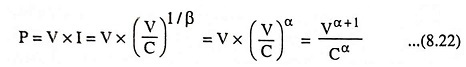
When the coefficient α = 5, the power dissipated by the varistor is proportional to the 6th power of the voltage. It means an increase of 12% in applied voltage will double the dissipated power. Consequently it is very important that the applied voltage does not rise above a certain maximum value, as otherwise the permissible rating will be exceeded.
This is even more cogent, as the varistors have a negative temperature coefficient, which means that at higher dissipation (and accordingly higher temperature) the resistance value will decrease and the dissipated power will increase further.
Temperature Coefficient: In the foregoing formulae temperature effects have not been taken into account. These, however, may not always be neglected, as the C-value has an appreciable negative temperature coefficient. The β value is practically independent of the temperature. With good approximation it may be expressed as
![]()
where Ct is C-value of varistor at t °C, C0 is C-value of varistor at 0°C, and a is temperature coefficient.
For different materials the value of a lies between – 0.0010 and – 0.0018. Thus, for circuits where the current is constant, the temperature coefficient on voltage lies between – 0.10 and – 0.18 per K. For circuits where voltage is constant the temperature coefficient on current lies between +0.4 and +0.8% per K depending on the value of β.
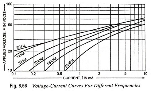
High Frequency Alternating Current: For low frequencies, the small capacitance of the varistor, does not affect the voltage dependency of the resistance. For high frequencies, however, this parallel capacitance may not be neglected. For low voltages and currents they may even determine the varistor impedance. At high voltages, the influence of the capacitance is less serious because; in that case the resistance over which the capacitance is shunted has decreased. In general the effect of the capacitance in high frequency circuits will be an apparent increase of β. A number of curves demonstrating this effect are given in Fig. 8.56.
Permissible Dissipation: The temperature which a varistor will attain is determined by the dissipated power, the heat conductivity of the material, the contact with, and the nature of the surrounding medium and by the ambient temperature. As already explained the dissipated power will increase rapidly with the increasing voltage.
The cooling per °C, though increasing slightly with temperature, depends mainly on the total surface area of the varistor.
For most varistors the maximum permissible body temperature is 125°C.
Zinc-Oxide Voltage Dependent Resistors: Unlike silicon-carbide types, the zinc-oxide varistors are mainly intended for applications requiring intermittent power dissipation, i.e. transient suppression and contact arc prevention. In their transient suppression role, the symmetrical mode of operation allows them to be connected directly across ac power lines carrying rms voltages of 30 to 460 V. They are capable of withstanding voltage or current pulses with a high peak energy level. A typical β for this type of varistor is 0.03. This means that, if the current through the varistor increases by a factor of 10 within the straight line portion of the characteristic, the voltage across it increases by a factor of 1.07.
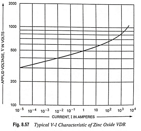
A typical V-I characteristic for one of these varistors is shown in Fig. 8.57. The upward turn of the characteristic (decreasing non-linearity) is due to the increasing influence of the linear series resistance of the component as its nonlinear resistance falls to very low values at extreme currents. A good approximation of the relationship between the applied voltage V and the current I in the curved portion of the characteristics is given by the expression
![]()
where RS is the series resistance of the varistor.
Normal Operating Conditions of the ZnO Varistor: Owing to the extreme non-linearity of the V-I characteristic of ZnO varistors, and the necessity to allow a margin for the extra dissipation during a transient, ensure that the maximum voltage applied across the varistor during normal operation never attains such a value that the specified average dissipation limit of the varistor is approached. This will be never the problem if the varistor is selected according to the figures for maximum rms voltage in the data sheet. The peak value of the sinusoidal voltage applied to the varistor must always be less than the minimum voltage specified at 1 mA. If the applied voltage is nonsinusoidal, the varistor should be selected on the basis of the specified maximum peak working voltage.