FET Common Source Amplifier with Unbypassed Source Resistors:
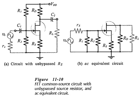
Equivalent Circuit – When an unbypassed source resistor (RS) is present in a FET Common Source Amplifier circuit, as shown in Fig.11-10(a), it also appears in the ac equivalent circuit, [Fig. 11-10(b)].
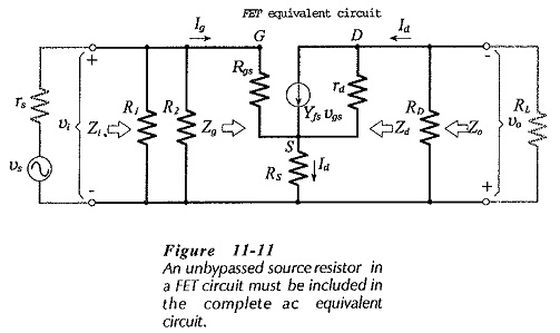
In the complete equivalent circuit RS must be shown connected between the FET source terminal and the circuit common input-output terminal, (Fig. 11-11). As with the previous equivalent circuit, the current directions and voltage polarities shown in Fig. 11-11 are those that occur when the instantaneous input voltage is positive-going. The presence of RS without a bypass capacitor significantly affects the circuit voltage gain.
Input Impedance:
An equation for the input impedance at the FET gate can be determined from vi and Ig. From Fig. 11-11,
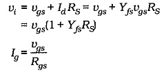
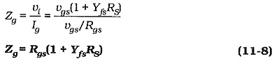
Equation 11-8 gives the input impedance at the FET gate terminal. The circuit input impedance is again given by,
![]()
In this case, Zg is much larger than R1||R2, so the circuit input impedance is determined by the gate bias resistors.
![]()
Output Impedance:
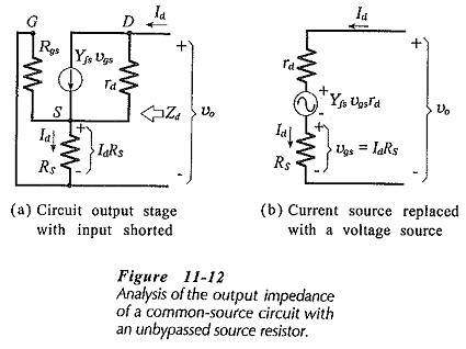
To calculate the circuit output impedance, the ac signal voltage (vs) is assumed to be zero, and an ac voltage (vo) is applied at the output, (see Fig. 11-12(a)]. The ac output current (Id) is calculated in terms of vo, then Zo is determined as vo divided by Id. Figure 11-12(a) shows that when vs is zero, the ac voltage across source resistor RS is applied as a gate-source voltage
![]()
Actually, IdRS is divided across rs||RG and Rgs. However, Rgs ≫rs || RG, so that all of IdRS is effectively applied as a gate-source voltage. The vgs produced in this way generates an ac drain current which opposes the drain current produced by vo,
![]()
Converting the current generator [(Yfsvgs) in parallel with rd] to a voltage generator [(Yfsvgsrd) in series with rd] gives the equivalent circuit in Fig. 11-12(b). The equation for the voltage drops around this circuit is,
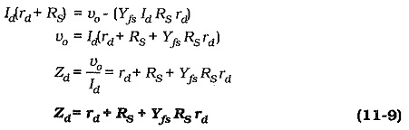
The circuit output Impedance is,
![]()
Because the output impedance at the FET drain terminal is much larger than the drain resistor (RD), the output impedance of the circuit with the unbypassed source resistor is still,
![]()
Voltage Gain:
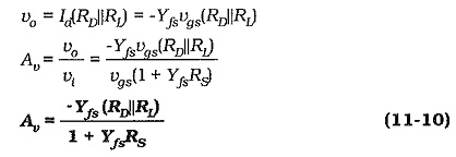
From the derivation of the input impedance equation,
![]()
and neglecting rd,
Usually,
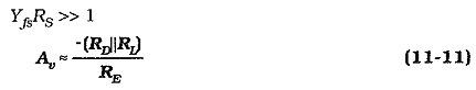
The voltage gain of a FET Common Source Amplifier circuit with an unbypassed source resistor can be quickly estimated using Eq. 11-11. For the circuit in Fig. 11-10(a), with RD = 4.7 kΩ, RS = 2.2 kΩ, and RL ≫ RD, Av ≈ -2.1.
Summary of Performance of CS Circuit with Unbypassed RS
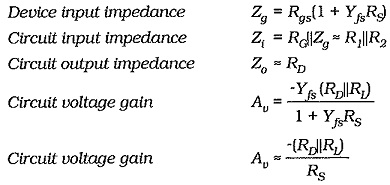
The most significant feature of the performance of a CS circuit with an unbypassed source resistor is that its voltage gain is much lower than that for a CS circuit with RS bypassed.