What is a Power Converter?
Solid-state power converter are employed for obtaining the appropriate form of electrical energy such as direct current or adjustable-frequency alternating current (required to operate most electronic circuits and motor drives) from fixed-frequency alternating current.
Types of Power Converters:
- AC to DC converters : AC to DC converters convert alternating current to direct current using a rectifier
- DC to AC converters : DC to AC converters take direct current and convert it to an alternating current of the desired voltage and frequency. These are inverters.
- DC to DC converters : These converters convert either a constant current to a variable or a constant direct current. These devices are also called choppers.
- AC to AC converters : AC to AC converters are often called cycloconverter or matrix converters. These devices convert an alternating current of a specific frequency or voltage from a line alternating current source to a different alternating voltage.
AC to DC Converter (Controlled Rectifier):
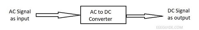
Rectification is a process of converting alternating current or voltage into a direct current or voltage. This conversion can be achieved by a variety of circuits based on and using switching devices. The widely used switching devices are diodes, thyristors, power transistors, power MOS etc. The rectifier circuits using only diodes as the rectifying elements are known as uncontrolled rectifiers because for a fixed value of ac input voltage, the output dc voltage is fixed and cannot be controlled. For some low-power devices where control of output voltage is not required, rectifier circuits using only diodes may be employed. Such circuits have the advantages of low cost and simple circuitry.
Rectifier circuits using thyristors are known as controlled rectifiers or ac to dc power converters. The basic principle of a controlled rectifier is to control the point in time at which the thyristors are allowed to conduct during each cycle. Thus, it is possible to select the time segments of the ac voltage waves which appear at the dc terminals, and the mean output voltage is controlled continuously. This process of control is called the phase control and the controlled rectifiers are, therefore, also called the phase-controlled rectifiers. Since thyristors are available in high voltage and large current ratings, controlled rectifiers using thyristors are employed in many high-power devices. A controlled rectifier may be a single-phase or 3-phase depending on whether the input is single-phase or 3-phase ac.
Controlled rectifiers are of two types namely fully-controlled and half-controlled. The fully-controlled rectifier uses thyristors as the rectifying elements and the dc output voltage is a function of the amplitude of the ac supply voltage and the point-on-wave at which the thyristors are triggered (called firing angle α). The half-controlled rectifiers consist of a mixture of diodes and thyristors, allowing a more limited control over the dc output voltage level than the fully-controlled rectifier. The half-controlled rectifier is cheaper than a fully-controlled rectifier of the same ratings but has operational limitations.
Uncontrolled and half-controlled rectifiers permit power to flow only from the ac system to the dc load and are, therefore, referred to as unidirectional, one-quadrant or semiconverters. However, with a fully-controlled rectifier it is possible, by control of the point-on-wave at which switching occurs, to allow power to be transferred from the dc side of the converter back into the ac system. When this occurs, operation is said to be in the inverting mode. The fully-controlled converters may, therefore, be referred to as bidirectional or two-quadrant converters. Thus it is possible for the phase-controlled converters to provide either a one-quadrant, two-quadrant or four-quadrant operation at its dc terminals. In a four-quadrant operation, two fully-controlled converters, connected back-to-back with one another, are used. Four-quadrant converters or dual converters provide the facility for bidirectional current flow through the load.
The converter type depends on the power to be handled and how much voltage ripple is tolerable. For low powers (below 20 kW), single-phase circuits are adequate but they themselves can take different forms. For high powers (above 20 kW), three-phase circuits are invariably employed.
DC to DC Converter (DC Chopper):
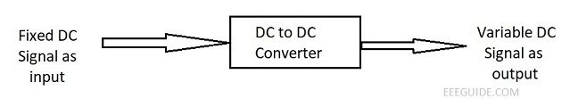
A dc chopper, also known as dc to dc power converter, is a static device (switch) used to obtain variable dc voltage from a source of constant dc voltage. Thus, chopper may be thought of as dc equivalent of an ac transformer as it behaves in an identical manner. Besides the saving in power, the dc chopper offers greater efficiency, fast response, lower maintenance, small size, smooth control, and, for many applications, lower cost than motor-generator sets or gas tubes approaches.
Solid state choppers due to their inherent advantages are widely employed in trolley cars, battery-operated vehicles, traction motor control, control of a large number of dc motors from a common dc bus, marine hoists, forklift trucks, mine haulers etc. They can also be used for regenerative braking in electric traction.
AC to AC Converter (AC voltage regulator):
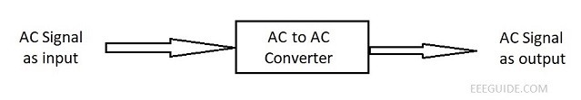
Thyristor-based ac voltage controllers using the phase control principle convert fixed alternating voltage directly to variable alternating voltage without a change in frequency. Applications of ac voltage controllers or regulators include domestic and industrial heating, transformer tap changing, lighting control, speed control of single-phase and three-phase induction motors etc. Earlier, the devices used for such applications were auto-transformers, tap-changing transformers, magnetic amplifiers, saturable reactors etc. But these devices are now being replaced by ac regulators using thyristors and triacs because of their high efficiency, flexibility in control, compact size and less maintenance. However, ac regulators using thyristors and triacs introduce objectionable harmonics in the circuit. AC regulators are classified as single phase or three phase. Each of these may be half-wave (unidirectional) or full-wave (bidirectional). Because of ac input, ac regulators are always line or naturally commutated and as such no complex commutation circuitry is required in these controllers.
Cycloconverter is defined as a power controller which converts input power at one frequency to output power at a different frequency with one-state conversion. Thus it is an ac to ac converter without any intermediate dc link. Cycloconverters can be classified as single phase-to-single phase, three phase-to-single phase, 3-phase-to-three phase devices. They may also be classified as step-down and step-up. In step-down cycloconverters, the output frequency is lower than the supply or input frequency. In step-up cycloconverters, output frequency is higher than supply frequency, Step-down cycloconverters use line or natural commutation while step-up cycloconverters need forced commutation. Generally step-down cycloconverters are in much use. The desired amplitude of output voltage can be had by changing firing angle of thyristors used in the circuit. With the advent of high-power thyristors cycloconverters are becoming more and more popular. At present, the applications of cycloconverters include speed control of high-power ac drives, induction heating, static VAR compensation, conversion of variable-speed alternator voltage to constant frequency output voltage for use as power supply in aircraft or shipboards.
DC to AC Converter (Inverter):
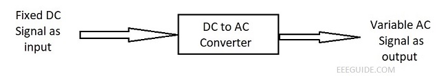
The dc to ac power converter are known as inverters. In other words, an inverter is a circuit which converts a dc power into an ac power at desired output voltage and frequency. The ac output voltage could be fixed at a fixed or variable frequency. The dc input supply may come from a battery, solar cells, fuel cells etc.
The conversion can be achieved either by transistors or thyristors. For low and medium power outputs transistorized inverters are used but for high power outputs, thyristors should be used. For low power outputs, self-oscillating transistorized inverters are suitable but for high power outputs, driven inverters are more common than self-oscillating ones. Moreover for multiphase ac output, there is no alternative other than driven inverters. The driven inverters have better frequency stability because a separate master oscillator is used for this purpose. For the applications in inverters, transistors have some edge over thyristors regarding the switching speed, simplicity in control circuits, higher efficiency and greater reliability. This is mainly due to the fact that thyristor inverters need extra circuits to turn thyristors off, moreover, additional complex logic circuits may be required to avoid false triggering and provide proper commutation timings. Thyristors can handle much higher load currents than transistors and consequently, for high power outputs, thyristors become more desirable than transistors.
The output voltage waveforms of an ideal inverter should be sinusoidal, but the output voltage waveforms of practical inverters are nonsinusoidal and contain certain harmonics. Square wave or quasi-square wave voltages may be acceptable for low and medium power applications, but for high power applications low-distorted sinusoidal waveforms are required. The output frequency of an inverter is determined by the rate at which the semiconductor devices are switched on and off by the inverter control circuitry and consequently, an adjustable frequency ac output is readily provided. The harmonic contents of output voltage can be reduced significantly by switching techniques of available high speed power semiconductor devices. The filtering of harmonics is not feasible when the output frequency varies over a wide range, and the generation of ac waveform with low harmonic content is important. When the ac output voltage of an inverter is supplied to a transformer or ac motor, this output voltage must be varied in conjunction with frequency to maintain the proper magnetic conditions. Some of the important applications of inverters arc: variable speed ac motor drives, induction heating, aircraft power supplies uninterruptable power supplies (UPS), high-voltage dc transmission lines etc.