Electric Converter:
Electric Converter – The speed of a dc motor can be varied by varying the armature voltage or the field current, for which a variable dc supply is required. The speed of an ac motor, on the other hand, can be varied by varying its supply frequency. In order to achieve the rated torque capability of the motor it is necessary to operate it at rated flux (maintained constant), which can be obtained by varying the applied voltage also. Hence, a variable voltage, variable frequency supply is required to control the speed of an ac motor.
With rapid developments made in the area of thyristors, power converters using them have become very popular in the control of electric drives. The variable dc voltage needed to control the speed of dc motors can be obtained by means of a phase controlled line commutated converter. The basic theory and important fundamentals of these converters are well known from the days of mercury arc rectifiers. A variable frequency supply is possible by means of inverters employing forced commutation if the ac side of the Electric Converter is unable to provide the necessary reactive power for the Electric Converter. The basic principles of inversion have been known for long, but the devices were not popular because of the poor dynamic properties of mercury arc rectifiers. With the advent of thyristors and developments in integrating circuits for the control of thyristors there has been a lot of development in the area of inverters making use of forced commutation. These find application in industry in the area of electric drives.
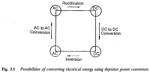
Electric Converter are systems used to transform or control electrical energy using the phase control of thyristors. A thyristor in these circuits periodically provides conducting and non-conducting states alternately, which are used to control the output voltage or output frequency or both. Figure 3.1 summarises several possibilities of converting electrical energy using power converters. The arrows indicate the direction of power flow and the circles, the type of source (ac or dc).
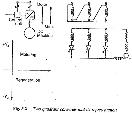
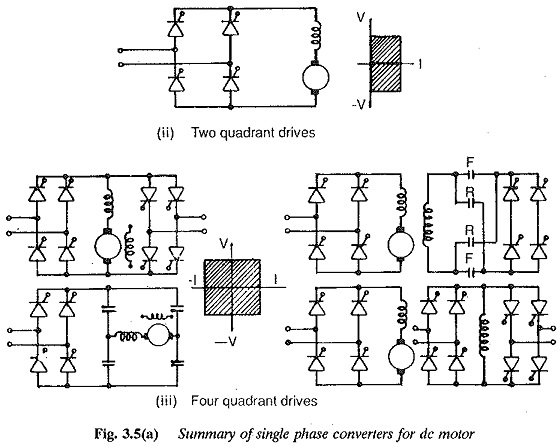
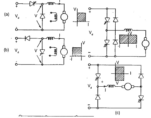
Converters, when used to control the speed of a dc motor, are called upon to provide a variable voltage. This is possible by converting the existing ac to dc. The process is called rectification and the converter is a phase controlled line commutated rectifier. The phase control of thyristors using a control voltage makes it possible to have a variable voltage at the output terminals. Sometimes, the converter is required to allow power flow from a dc load to an ac supply, e.g. during the regenerative braking of a dc motor. The converter performs a function called synchronous inversion. A Electric Converter which can perform both rectification and inversion is called two quadrant converter. The speed of a dc motor can be varied very smoothly and continuously with it. The two quadrant representation is shown in Fig. 3.2.
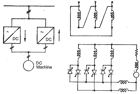
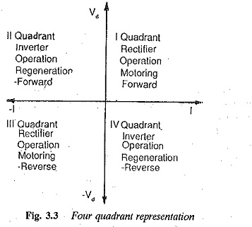
A dc motor is sometimes required to operate as a variable speed motor in both directions of rotation, with a possibility of regenerative power transfer to the ac supply system. The operation is called four-quadrant operation. Two two quadrant converters connected back to back provide this reversible drive. Four quadrant operation is shown in Fig. 3.3. Depending upon the polarity of voltage Vd and current Id, the voltage-current plane of the dc system can be divided into four quadrants. When both Vd and Id have the same sign, the power is delivered to the dc system. This is possible in the I and III quadrants. When they have opposite signs the power flows from dc to ac.
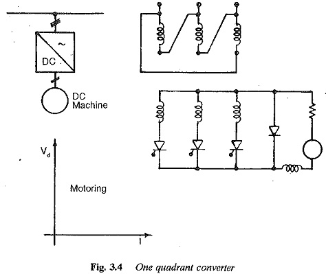
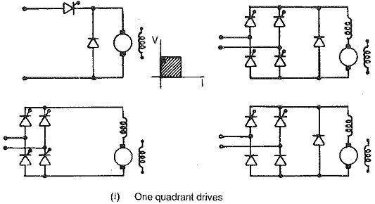
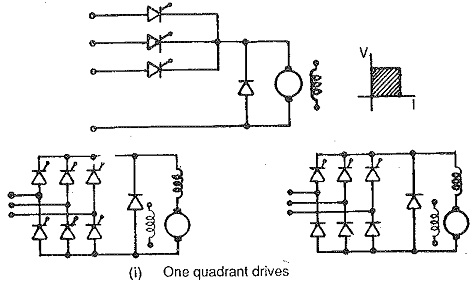
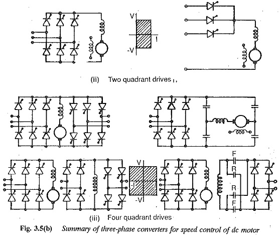
Certain applications of dc motor drives may require operation only in the first quadrant. In such a case the converter feeding the motor is called a one quadrant converter. As no regeneration is required, diodes can be used at some points as a substitutes for the thyristors. This, besides reducing the cost of the converter, improves its performance with respect to the power factor, and line harmonics. One quadrant operation of the converter is depicted in Fig. 3.4. A summary of the converters for controlling the speed of a dc motor from single phase and three-phase supplies is given in Fig. 3.5.
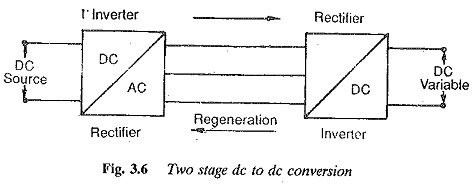
A variable dc voltage can be made available to a de motor from a constant dc voltage using a two stage conversion. A two stage dc to dc converter has an intermediate ac link. DC is first converted to ac by means of an inverter employing forced commutation. This ac is then rectified to variable dc. The schematic is shown in Fig. 3.6.
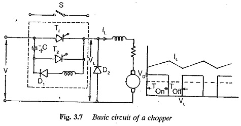
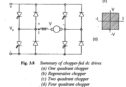
The conversion of a constant dc voltage to a variable dc voltage using a single stage conversion equipment, known as a chopper, is very popular. The basic circuit and its operation is shown in Fig. 3.7. By operating the switch S at a constant frequency of ON and OFF with appropriate control, the average value of output voltage can be varied. The switch S is called the thyristor chopper. The FWD allows the flow of load current when the switch S is open, especially when the load is inductive. When the FWD conducts, the energy stored in L is partly dissipated in. R. By suitably selecting the chopper frequency and load inductance L the output current can be made to have a very small ripple content. A dc chopper is therefore suitable for controlling the speed of a dc motor efficiently. Four quadrant operation is possible. Figure 3.8 gives a summary of the operation of a dc motor on one-two- and four-quadrant choppers. The dc chopper circuit is very simple and straightforward.
 .
.
The block diagram for the control of an ac machine from a constant ac supply is shown in Fig. 3.9. The variation of stator voltage at constant frequency is obtained from a three phase voltage controller as shown in Fig. 3.9(a). In the other schemes shown in Fig. 3.9(b) and Fig. 3.9(c) both machine voltage and frequency are varied simultaneously so that air gap flux is constant. Both machine voltage and frequency can be independently varied using control voltage (Vst1) of line side converter and the motor side converter (Vst2). They are varied so that optimum magnetic flux conditions exist in the motor corresponding to the rated torque. This provides an efficient operation of the motor, providing constant torque at every speed.
When speed control of the ac motor is required from a 3-phase system of constant frequency, the line commutated phase controlled converter and the force commutated inverter are connected in series, as shown in Fig. 3.10. The interconnection of these Electric Converter is by means of energy storage elements which decoupie the converters so that the disturbances on the power system feeding the line side converter have no effect on machine behaviour. Such a converter is called a dc link converter. Both the converters are linked by means of a dc voltage or dc current. The former is called a voltage source inverter, with the motor impressed with voltages, and is shown in Fig. 3.11. The dc link voltage is applied to the motor phases alternately by controlling the inverter. The latter is called a current source inverter, and the motor is impressed with currents. The two differ in several aspects of performance also. In the motor operation, the line side converter operates as a rectifier and the one on the machine side as an inverter. During regeneration their functions are reversed, i.e. the machine side converter operates as a rectifier and the line side one as an inverter.
An inverter requires voltage control so that the operating flux of the motor can ensure efficient operation. This can be achieved external to the inverter. The control angle of the line side Electric Converter is varied to provide the required voltage while the machine side converter is controlled to provide the required frequency. The inverter operates at variable dc voltage. The main drawback is the insufficient voltage available for commutation at low speeds, which consequently puts a limit on the lower speeds. Sometimes voltage control can be obtained in the inverter itself, using the principles of PWM or PSM. The inverter operates at constant dc link voltage, and is controlled to vary both the frequency and amplitude of the voltage. These are invariably voltage source inverters which require an additional converter during regeneration. The output voltage waveforms of these converters are shown in Fig. 3.12
In the case of a current source inverter, shown in Fig. 3.13, the dc link current is allowed to flow through the phases of the motor alternately by suitably controlling the inverter. The inverter does not require feedback diodes and the configuration is very simple. Regeneration is simple and straightforward. The disadvantage is that it is not suitable for multimotor drives.
Variable frequency supply to an ac motor can also be provided by a cycloconverter which is a single stage (ac to ac) frequency converter having both voltage and frequency control. The output frequency of a cycloconverter can be at most 1/3 times the supply frequency. This gives a speed control in, the range 0-33% of base speed. Line commutation can be made use of. The output voltage waveform has less ripple content. The schematic of a cycloconverter feeding a 3-phase ac motor is shown in Fig. 3.14.
Inverters can have natural commutation using load voltages if the load is capable of providing the necessary reactive power for the Electric Converter. Such a case occurs when a variable frequency converter feeds a synchronous motor. An overexcited synchronous motor can provide the reactive power necessary for commutation and the machine voltages can be made use of to turn off the thyristors. A current source inverter or a cycloconverter feeding a syn chronous motor employs machine commutation. The former does not require a commutation circuit and has a very simple configuration. The latter does not have frequency limitations and the speed range can go up to base speed. The firing signals to the thyristors of the converter are derived from the motor position. The motor in this case is called self controlled and has a behaviour similar to that of a dc motor.