Single Phase Dual Converter Circuit Diagram with Four Quadrant of Operation:
We have seen that Single Phase full Converters with inductive loads allow only a two-quadrant operation. If two of these full converters are connected back to back, it is known as Single Phase Dual Converter as depicted in Fig. 27.20 (a) , both the output voltage and the load current flow can be reversed. This system provides a four-quadrant operation as shown in Fig. 27.20 (b) and is called a dual converter. Dual converters are normally used in high-power variable speed drives. If α1 and α2 are the delay angles of converters 1 and 2 respectively, the average output voltages are Vdc1 and Vdc2.
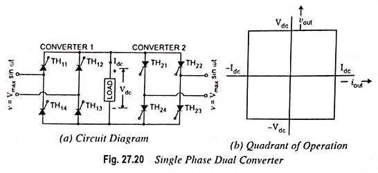
The delay angles are controlled such that one converter operates as a rectifier and the other operates as an inverter; but both converters generate the same output voltage.
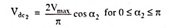
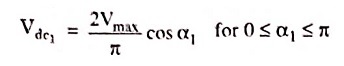
The average output voltage of converter 1 is given by
The firing angle α2 of converter 2 will be equal to (π – α1) and when converter 2 is operating as an inverter