Two Quadrant Chopper:
Sometimes a chopper may be required to provide a two quadrant operation by retaining the current direction in both motoring and braking modes. Such a Two Quadrant Chopper is shown in Fig. 3.86, and its waveforms in Fig. 3.87. The chopper permits a change in the polarity of terminal voltage keeping the direction of current constant. In Fig. 3.86 S1 and S2 are the choppers working as electronic switches and D1 and D2 are the feedback diodes. Assuming continuous conduction, both S1 and S2 operate simultaneously.
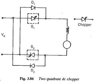
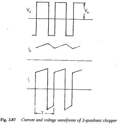
When they are ON, the load current Id increases, with the rate of rise depending upon the back emf and torque of the machine. When they are OFF, the load current is fed to the supply through the diodes D1 and D2. The current decreases in this stage. From Fig. 3.87, it is clear that the load voltage is effectively negative when the diodes conduct. The average value of the output voltage of the chopper
Vda is zero for a = 0.5, the output voltage is an ac waveform with average voltage equal to zero. For a > 0.5 the average value of the dc voltage is negative. The chopper works in the regeneration mode. The power flows from the load to the supply and the dc machine operates as a generator. For control ratios a c 0.5, the operation is similar to the inversion of a line commutated converter (α > 90°). For a > 0.5 the chopper has normal operation. The power flows from the supply to the load. This operation of the chopper is similar to rectification of a line commutated converter (α < 90°). For, a = 0.5 the load voltage is zero. The control characteristic of a two quadrant chopper is shown in Fig. 3.87.
Four quadrant chopper
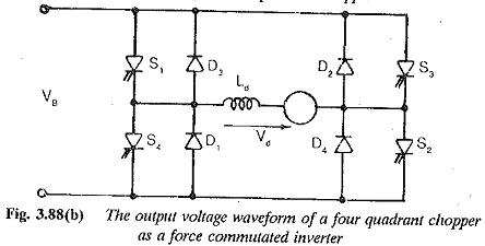
A chopper circuit for four quadrant operation is shown in Fig. 3.88(a). This is obtained by connecting two Two Quadrant Chopper antiparallel to each other. The circuit has characteristics similar to a dual converter. The load side voltage and current waveforms have both polarities.
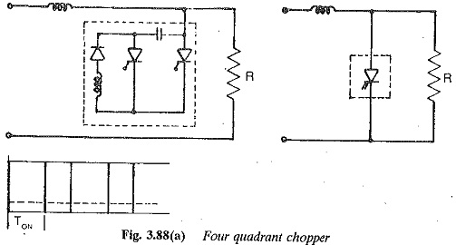
The dc machine connected to this chopper can be accelerated, braked and controlled so as to have smooth speed variation in both directions of rotation. This four quadrant chopper is a starting point for the development of a force commutated inverter, to obtain a variable frequency voltage at the load terminals from a constant dc supply. The sketch of the output voltage of the circuit operating as an inverter is given in Fig. 3.88(b).