Performance of Chopper in Steady State Condition:
Assuming Steady State Condition of the chopper, we have during TON
![]()
The solution of Eq. 3.89 is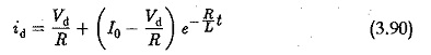
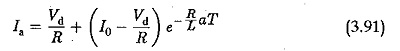
where Io is the current at the starting of TON. At TON = aT, the current is
when the thyristor is OFF, free wheeling takes place and the operation is described by
![]()
which has the solution
![]()
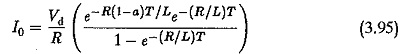
Again taking t = 0 at the start of TOFF, at the end of TOFF = (1 — a)T the current is
![]()
Using these equations
The value of Ia can also be determined. The difference Ia – lo gives the peak to peak amplitude of the ripple superimposing the average dc current.
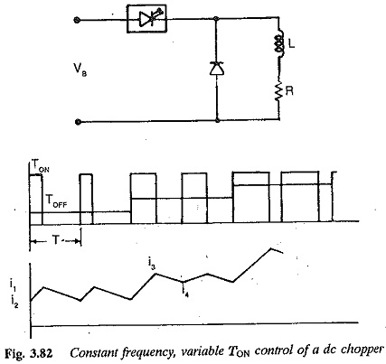
The amplitude of the ripple depends upon the time ratio a. Figure 3.82 depicts the variation of load current for different values of a. It can be seen from the figure that the ripple amplitude is maximum at a = 0.5 and decreases for both a > 0.5 and a < 0.5. These can be derived for d.c. series motor assuming it to be an R-L load using the above equations. For a separately excited motor, the back emf has to be considered. Assuming no losses in the motor, E = aVd. In this case,
![]()
solving which we get
![]()
The current at the end of TON = aT is
![]()
from which![]()
The solution for i shows a linear variation of current. The ripple superimposing the average dc current becomes triangular. The peak value of the ripple is
![]()
The rms value of the current
![]()
From Eq. 3.100, we can see that the ripple has a maximum amplitude at a = 0.5. The ripple makes the load current discontinuous at very low values of load current. This lower limit of load current is influenced by the type of load. For R-L loads one can go down to very low values of current if the time constant is sufficiently large. For the back em( loads discontinuous operation occurs early. The lower limit of load current is high in this case.
The ripple in the load current can basically be reduced by increasing the chopper frequency and by introducing an extra inductance in the load circuit.