Performance of Circuit Breaker System Requirements:
Analysis of circuit interruption and the foregoing discussion of various circuit breakers apply to circuit breakers in practice if they had ideal switching characteristics. The ideal circuit Breaker System has a negligible are voltage and has the ability to develop instantaneously infinite arc-gap resistance at natural current zero. In practice Breaker System do not behave ideally and therefore it is necessary to consider the conditions that actually occur in three main types of circuit breakers.
- Oil circuit breakers with plain break.
- Oil breakers with arc-control device (self-blast).
- Forced-blast breakers.
Voltage Distribution in Oil Circuit Breakers with Plain Break:
In this type of circuit Breaker System because of the nature of the interruption process, the conditions following the final current zero tend to be unstable in character. Usually a long arc is drawn and the arc resistance does not reach infinite value at current-zero with the result that some leakage current flows. This leakage current can play a dual role, i.e. either it can make the performance of the breaker a success or it can vitiate the interruption process.
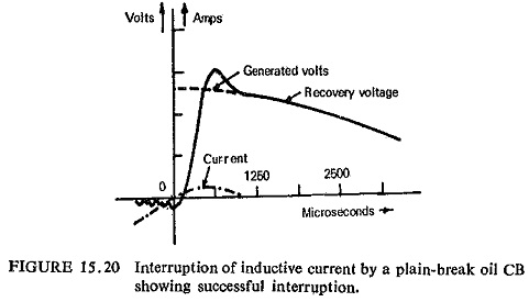
The leakage current damps the restriking voltage oscillations, thereby reducing circuit severity, and make interruption easier (Fig. (15.20)). At the same time, the leakage provides a form of resistance grading which helps in equalizing the distribution of the restriking voltage across the multibreak system, overcoming the inherent voltage distortion caused by stray capacitance, which would otherwise have rendered most of the interrupting gaps virtually useless, because they carry but a small share of the overall voltage. This can be illustrated by taking a simple case of a bulk oil circuit breaker with two breaks per pole.
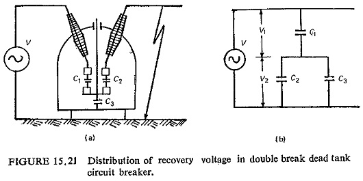
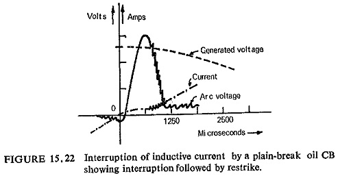
Figure (15.21) shows the circuit breaker and various capacitances between the contacts and between the cross bar and the earthed tank, the equivalent circuit is also shown. In the event of a phase-to-ground fault, the voltage distribution between circuit breaker contacts can be easily found from the equivalent circuit. It can be seen that
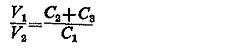
Now C1 and C2 are of the same order, but C3 is much greater than C1 or C2, hence V1≫V2. Typical values of capacitances across contacts (C1, C2) are 10 to 40 μμF and the stray capacitance to ground (C2) 40 to 100 μμF. However, if there is an appreciable leakage current through the arc, the capacitance voltage control may be swamped. The leakage current may increase with rising voltage stress, in which case the arc restrikes (Fig. (15.22)). In extreme cases if this happened in the fully open position, the energy released is sufficient to damage circuit breaker.
As the variable nature of leakage current cannot be predicted, plain-break oil circuit breakers are used for lower breaking capacities and up to 11 KV only.
Voltage Distribution in Oil Circuit Breakers with Arc Control Devices:
The controlled nature of turbulence and resultant deionization in this type eliminates the erratic operation of the plain-break by virtually eliminating the leakage current, but it also eliminates the useful voltage damping and voltage distribution function which this current had performed in the plain-break type. Voltage distribution of such a type is shown in Fig. (15.23).
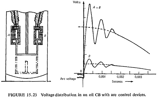
Under these conditions, capacitance will control the voltage distribution and only a small part of the voltage duty is carried by the second break, it has been shown above that a major part of the voltage comes across the first break, i.e. capacitance C1. In this respect the second break is of little value electrically. But if the advantages of the multibreaks are to be derived then it has to be fitted with positive voltage grading and damping devices in the form of shunt resistors. These additions though expensive, make the ehv oil circuit breaker reliable by performing consistently the function the leakage current had previously carried out in the plain-break oil circuit breaker. A desirable compromise would be for leakage current to be deliberately retained, but with effective control. No means of achieving this have as yet been suggested, and this problem may remain insoluble because of the difficulty of control problem it presents.
A problem associated with the self-blast circuit breaker is the interruption of low currents when the pressure generated is also small and the system RRRV is high. These led to longer arc-duration when interrupting small currents than when interrupting large currents. This is overcome in the forced blast breakers.
Speed of Operation:
Uptil now fault clearance times of 140 ms have been acceptable; this allows 60 ms for the relays and 80 ms for the Breaker System. Minimum oil circuit breakers meet this requirement very easily. These timings can still be reduced by improved designs. Fault clearance timings of 3 cycles are being specified nowadays. This allows one cycle for the relay and two cycles for the breaker. Attempts are being made to reduce the operating times of circuit breakers to less than two cycles. A most promising development in this regard however appears to be the use of vacuum circuit breakers.
Terminal Short-Circuit and RRRV:
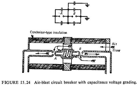
These two factors are against each other during current interruption at current zero. Under short circuit, the stress on circuit Breaker System depends on the current and rate at which the voltage rises across the contacts of the circuit breaker. The rate of rise of the voltage across the circuit breaker contacts just after current zero is defined by the capacitance, inductance and resistance of the system. The amplitude and frequency of this voltage which is called transient restriking voltage result in an RRRV which conditions the restriking after current zero. In the forced blast breakers the rate of rise of dielectric strength is initially low. Due to this the air blast circuit breaker is inherently sensitive to RRRV. Forced-blast designs have special advantages in the high voltage field, where rapid interruption is important; they have been developed in muttibreak form employing capacitance voltage-grading across the gaps (Fig, (15.24)).
With both oil blast and air blast, the velocity of dielectric is independent of fault current. It follows that these circuit Breaker System can interrupt low currents at very high RRRV with the same arc duration as at full rating; therefore the increase in arc duration that is a characteristic of the self-blast type under low-current conditions is avoided. On the other hand, no increase in velocity of the dielectric is obtained at heavy currents; in fact, it is usually reduced, so that the RRRV which forced-blast circuit breakers can then withstand is somewhat lower than at small currents. This matches with the characteristic of high voltage systems. Oil circuit breakers are practically insensitive to RRRV at the location of the circuit Breaker System. Due to this an exact idea of RRRV at the location of the circuit breaker is not necessary. Moreover there is no necessity of derating the circuit breakers even when installed in locations having very high RRRVs.
Interruption of Small Inductive Currents:
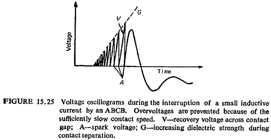
When small inductive currents, such as those flowing through transformers on no load are interrupted before natural zero, i.e. current chopping voltage oscillations, which lead to transient overvoltages result. The voltage oscillations are caused both on the line as well as on the supply side. The magnitude of overvoltages will usually be high on the line side due to high impedance of the transformer. The overvoltages produced during interruption of small inductive currents can be limited by repetitive restrikes in the circuit breakers (Fig. (15.25)) or by fitting shunt resistors of suitable value across the circuit breaker.
Though an overvoltage factor of 3.5 can sometimes be tolerated, a factor of 2.5 is now frequently specified.. Oil breakers with arc control devices operate satisfactorily under these conditions while forced-blast breakers may produce overvoltages and special means have to be provided to prevent them. Normally minimum oil circuit breakers do not give an overvoltage factor exceeding 2.5. However, if lower overvoltage factor is required, these breakers can be fitted with shunt resistors.
Interruption of Capacitive Currents:
Modern circuit breakers are required to interrupt long transmission lines on no load very frequently. Under certain circumstances these interruptions may produce overvoltages. With each restrike the voltage on the line side surges up, but in practice the overvoltages do not attain dangerous values due to damping of the oscillations. Thus for interruption of capactive currents the ideal is restrike free performance of the circuit breaker.
Minimum oil circuit breakers are not entirely restrike free unless specially designed for this duty. For most of the systems up to 132 KV one or two restrikes are permitted provided the maximum overvoltage is limited to 2.5 to 3 times the normal. For system voltages of 220KV and above it is necessary to have restrike free circuit breaker. Minimum oil circuit breakers of multibreak design and having artificial oil injection are restrike free and do not produce overvoltages while interrupting capacitive currents or disconnecting unloaded lines. Air-blast circuit breakers are also restrike free and hence are preferred for system voltages of 220KV and above.
High Speed Reclosing:
Many faults in the power systems are transient in nature and cause disconnection of the circuit without damage to the lines or plant. The supply in such cases can be restored by momentary isolation of the faulted line followed by reenergizing after a predetermined time. For successful auto-reclosing the characteristics of circuit breakers and networks have to be taken into consideration. These can be broadly defined as
- The fault current must be interrupted in the shortest possible time, to avoid transient fault establishing into a sustained fault.
- The supply should be resumed as soon as possible to minimize inconvenience to consumer.
- A minimum dead time must be allowed for dielectric strength at the fault point to recover before line is reenergized.
- The circuit breaker mechanism must be allowed time to establish before reclosure is attempted.
For performing auto-reclosing duty, the operating mechanism of the circuit breaker is arranged in such a way that if after first reclosing the fault is not cleared the breaker performs a second interruption after which the system is permanently isolated from the fault. The dead time is usually in the range of 0.2 to 0.6 second.
Short Line Fault:
If a fault occurs close to sub-station the initial rate of rise of restriking voltage is high but the amplitude is low. If a fault occurs away from the breaker the initial rate of rise is low but amplitude is high and the value of the short-circuit current is also small. The breaker will not be overstressed in both the cases. Between the above two cases there are intermediate ranges (in most cases from 500 m to 6km) where both the amplitudes as well as rate of rise of first loop may be of such value as to cause the restrike in the breaker.
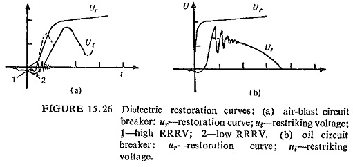
Minimum oil circuit breakers are not sensitive to short-line faults. This is due to the fact that dielectric restoration curve of oil circuit breaker shows a steep rise and then flattens (Fig. (15.26)), and in most cases the dielectric restoration curves are above restriking voltage curve.