Series Diode Configurations with DC Inputs:
The approximate models discussed in preceding section are used for investigation of a number of series diode configurations with dc inputs. This establishes a foundation in diode analysis that will carry over into the sections. The procedure described can, in fact, be applied to networks with any number of diodes in a variety of configurations.
For each Series Diode Configurations, the state of each diode is first determined which diodes are “on” and which are “off’? Once determined, the appropriate equivalent can be substituted and the remaining parameters of the network determined.
In general, a diode is in the “on” state if the current caused by the applied sources is such that its direction matches that of the arrow in the diode symbol, and the diode voltage VD exceeds V0(0.7 V in case of silicon and 0.3 V for germanium diode).
For each Series Diode Configurations, mentally replace the diodes with resistive elements and note the resulting current direction. If the direction of resulting current “matches” with the arrow in the diode symbol, the diode is in conducting or “on” state. If the diode is in the “on” state, diode can be replaced by a 0.7 V drop across the element or the network is redrawn with the V0 or VK equivalent circuit. It is preferable to include the 0.7 V drop across each “on” diode and draw a line through each diode in the “off” or open state.
Let us consider a series circuit, shown in Fig. 7.25, to understand the approach described above.
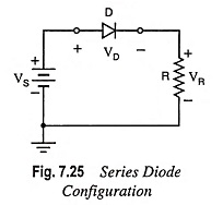
The state of the diode is first determined by mentally replacing the diode with a resistive element as shown in Fig. 7.26(a). The resulting direction of current I matches with the arrow in the diode symbol, and since VS exceeds V0 or VK, the diode is in the conducting (or “on”) state. The network is redrawn, as depicted in Fig. 7.26 (b), with the appropriate equivalent model for the forward-biased semiconductor diode. Note for future reference that the polarity of VD is the same as would result if in fact the diode were a resistive element. The various relations between different voltages and current are given below:
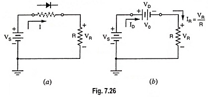
Voltage drop across diode,
![]()
Voltage drop across resistor R,
![]()
Diode current,
![]()
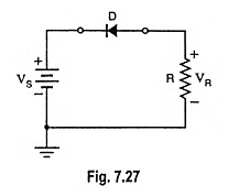
Now let us consider the diode connected in reverse-biased mode, as shown in Fig. 7.27.
If the diode is replaced mentally with a resistive element as depicted in Fig. 7.28 (a), it is revealed that the direction of flow of resulting current does not match the arrow in the diode symbol. It means that the diode is in “off” state and the resultant equivalent circuit will be as shown in Fig. 7.28 (b). Open circuit will not allow the current to flow in the circuit i.e., ID = IR = 0.
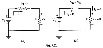
Voltage drop across resistor,
![]()
and Voltage drop across diode,
![]()