Four Phase Stepper Motor:
Four Phase Stepper Motor – The stepper motor is a special type of synchronous motor which is designed to rotate through a specific angle (called a step) for each electrical pulse received by its control unit. Typical step sizes are 7.5°, 15° or larger. The stepper motor is used in digitally controlled position control systems in open loop mode. The input command is in the form of a train of pulses to turn a shaft through a specified angle.
There are two advantages in using stepper motors. One is their compatibility with digital systems and secondly no sensors are needed for position and speed sensing as these are directly obtained by counting input pulses and periodic counting if speed information is needed. Stepper motors have a wide range of applications; paper feed motors in typewriters and printers, positioning of print heads, pens in XY-plotters, recording heads in computer disk drives and in positioning of work tables and tools in numerically controlled machining equipment. The range of applications of these motors is increasing as these motors are becoming available in larger power ratings and with reducing cost.
Elementary operation of a Four Phase Stepper Motor with a two-pole rotor can be illustrated through the diagram of Fig. 10.32.
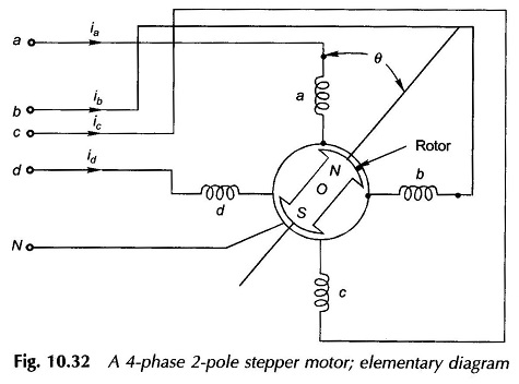
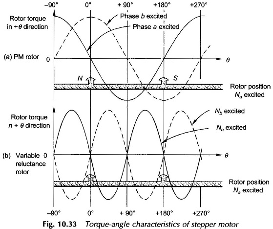
Let us assume that the rotor is permanent magnet excited. Such a rotor aligns with the axis of the stator field with torque being proportional to the sin θ, θ being the angle of displacement between the rotor axis and stator field axis. The torque-angle characteristics of Four Phase Stepper Motor is drawn in Fig. 10.33(a) with phase a excited and also with phase b excited. It is easily observed that the stable position of the rotor corresponds to that angle at which the torque is zero and is positive for smaller angles and negative for larger angles. Thus with phase a excited, the stable (or locked) position is θ = 0° but not θ = 180° (unstable) and the torque has a maximum positive value at θ = – 90°. It is therefore easily concluded that each excitation pattern of phases corresponds to a unique position of the rotor. Therefore the excitation sequence a, b, c, d, a … causes the rotor to move in positive sequence in steps of 90°.
With rotor in position θ = 0 and a and b both excited the rotor will move to 45°, which is a stable position (net torque due to a and b zero and torque-angle slope negative). So excitation sequence a, a + b, b, b + c, c … make the rotor to move forward in steps of 45°. Patterns for phase winding excitations can be easily visualized for steps of 22.5°, 11.25°, and smaller per pulse input to the circuit. Another feature of a PM stepper motor is that, when excited, it seeks a preferred position which offers advantage in certain applications.
Consider now that the rotor (projecting pole) is made of just ferromagnetic material (no permanent magnet). The device now behaves as a variable-reluctance motor. The ferromagnetic rotor seeks the position which presents minimum reluctance to the stator field, i.e. the rotor axis aligns itself to the stator field axis. In Fig. 10.32 with phase a excited, this happens at θ= 0° as well as θ = 180° in which positions the torque on the rotor is zero. At θ = 90° the rotor presents infinite reluctance to the phase ‘a’ axis and so the torque has also a zero there. Thus the rotor torque is a function of sin 2θ as drawn in Fig. 10.33(b). For a reductance stepper motor there are two possible stable positions for a given excitation or set of excitations.