Variable Reluctance Stepper Motor:
Variable reluctance stepper motor can be of single-stack or multi-stack type.
Single Stack Variable Reluctance Motor:
A variable reluctance stepper motor has salient pole (or tooth) stator and rotor. While rotor has no windings, stator has concentrated coils placed over the stator poles (teeth). Stator winding phase number depends on the connection of stator coils. When the stator phases are excited in a definite sequence from a dc source with the help of semiconductor switches, resultant air-gap field steps around and rotor follows the axis of air-gap field due to reluctance torque developed by the tendency of magnetic circuit to occupy the position of minimum reluctance.
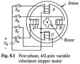
A four-phase, 4/2-pole (4-poles in the stator and 2 in rotor), single-stack, variable reluctance stepper motor is shown in Fig. 8.1. Four-phases A, B, C and D are connected to dc source with the help of semiconductor switches SA,SB,SC and SD respectively. Phases are excited in the sequence of A, B, C, D, A. When A is excited, the reluctance torque causes rotor to turn, until it aligns with the axis -of phase A. The rotor is stable in this position and cannot move until phase A is de-energised. Next, phase B is excited and A is disconnected. Rotor turns through 90° in clockwise direction to align with the resultant air-gap field which now lies along the phase B axis. Thus, as the phases are excited in the sequence A, B, C, D, A, rotor turns with a step of 90° in clockwise direction. Direction of rotation can be reversed by reversing the sequence of switching the phases, that is A, D, C, B, A. Direction of rotation depends only on the sequence in which phases are switched and is independent of the direction of currents through the phases.
The step-angle can be reduced from 90 to 45° by exciting phases in sequence A, A + B, B, B + C, C, C + D, D, D +A, A. When phase A is excited, the rotor aligns with the axis of A. When, both phases A and B are excited, the resultant air-gap field axis, and therefore, rotor turns by 45° in the clockwise direction. Rotor can be turned in anticlockwise direction with a step of 45° by switching phases in sequence of A, A + D, D, D + C, C, C + B, B, B + A, A. This technique of gradually shifting excitation from one phase to another (e.g. from A to B with an intermediate step of A + B) is known as microstepping and is used to realise smaller steps.
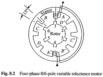
By various combinations of phase number, and stator and rotor pole numbers, various step sizes are realized. As an example, a four-phase, 8/6-pole, single-stack Variable Reluctance Stepper Motor is shown in Fig. 8.2. Winding is shown only for phase A. The rotor turns with a step- angle of 15°. For clockwise rotation, phases are switched in the sequence of A, B, C, D, A and for anticlockwise rotation, they are switched in the reverse sequence of A, D, C, B, A.
When phase A is energised, the rotor turns until a pair of its poles (1 and 4 here) align with the axis of phase A (Fig. 8.2). If B is excited, the rotor turns by 15° in the clockwise direction until rotor poles 3 and 6 are aligned with the axis of phase B. Here also, the microstepping can be adapted to reduce the step size. For clockwise rotation with a step size of 7.5° the sequence A, A + B, B, B + C, C, C + D, D, D + A, A can be used.
In order to have self starting capability and bidirectional rotation, the stator and rotor pole numbers have to be different.
Multi-Stack (or in-Stack) Variable Reluctance Motor:
These are used to obtain smaller step sizes, typically in the range of 2 to 15°. Although three stacks are common, a multi-stack motor may employ as many as seven stacks.
A m-stack motor can be viewed as consisting of m identical single stack variable reluctance motors with their rotors mounted on a common shaft. The stators and rotors have the same number of poles (or teeth), and therefore, same pole (tooth) pitch. While the stator poles (teeth) in all m stacks are aligned, the rotor poles (teeth) are shifted by 1/m of the pole pitch from one another. All the stator pole windings in a given stack are energised simultaneously, unlike the single-stack motor, where only the winding on single pair of poles are energised. Since all the stator pole windings in a given stack are excited simultaneously, the stator winding of each stack forms one phase. Thus the motor has the same number of phases as the number of stacks.
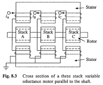
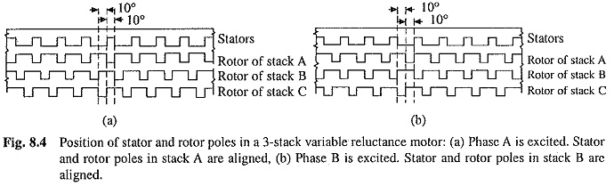
Figure 8.3 shows the cross-section of a three stack (three-phase) motor parallel to the shaft. In each stack, stators and rotors have 12 poles. While the stator poles in the three stacks are aligned, the rotor poles are offset form each other by one-third of the pole pitch or 10°. Relative positions of stator and rotor poles for the three stacks when phase A (i.e. stator of stack A) is excited is shown in Fig. 8.4(a). Rotor poles of stack A are aligned with the stator poles. Now if phase A is de-excited and B excited, rotor poles of stack B will get aligned with the stator poles. Thus, rotor will move by one-third of the pole pitch in anticlockwise direction (Fig. 8.4(b)). Now if phase B is de-excited and C excited, rotor will move by another one-third of pole pitch in the anticlockwise direction. When phase C is de-excited and A excited, rotor will have moved by one pole pitch compared to its position in Fig. 8.4(a).
The operation of a motor where stator stacks are aligned but rotor stacks are offset from each other is considered above. In alternative design the rotor stacks are aligned and stator stacks are offset.
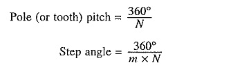
Let N be the number of rotor poles (or teeth) and in the number of stacks or phases. Then
The variable reluctance motors, both single and m-stack types, have high torque to inertia ratio, giving high rates of acceleration and fast response. They do not have detent or residual torque-torque acting on the rotor to oppose its movement when no current is flowing in the stator coils. Detent torque is important in some applications, e.g. when the power is switched off it helps the rotor to retain its position.