Switched Reluctance Motor:
The switched reluctance motor (SRM) has both salient pole stator and rotor, like variable stepper motor, but they are designed for different applications, and therefore, with different performance requirements. A stepper motor is designed to make it suitable for open loop position and speed control in low power applications, where efficiency is not an important factor. On the other hand a switched reluctance motor is used in variable speed drives and naturally designed to operate efficiently for wide range of speed and torque and requires rotor position sensing. It may also be noted that the switched reluctance motor is quite different from the synchronous reluctance motor. They have two major differences. In order to have self-starting capability and bidirectional control, the rotor of a switched reluctance motor has lesser poles than the stator, whereas a synchronous reluctance motor has the same number of poles on stator and rotor. They use different stator constructions; while the synchronous reluctance motor has a cylindrical stator with distributed winding, the Switched Reluctance Motor stator has salient pole stator with concentrated coils like a dc motor. As rotor has no winding, a Switched Reluctance Motor is even more rugged than the rugged squirrel-cage induction motor.
In Switched Reluctance Motor, though various combinations of stator and rotor pole numbers are possible, the commonly used are 8/6 and 6/4. As already stated, rotor does not have any winding. The stator has concentrated coils and diametrically opposite coils are connected, in series or parallel, to form one phase. Thus, motors with pole numbers 8/6 and 6/4 will have four and three phases, respectively.
Operation and Control Requirements:
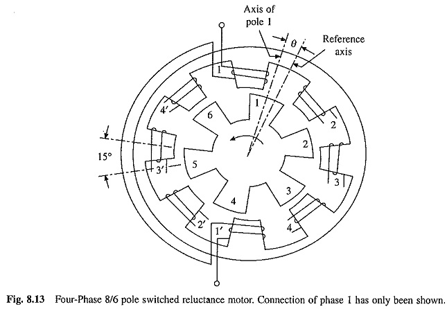
A four-phase, 8/6 pole switch reluctance motor is shown in Fig. 8.13. When a stator phase is excited, the reluctance torque make the rotor to move toward the position of minimum reluctance.
As rotor reaches the position of minimum reluctance, excitation is shifted to the next phase, thus shifting the position of minimum reluctance ahead of rotor. Hence, with the help of rotor position sensores, position of minimum reluctance is continuously shifted by shifting excitation from one phase to another and the reluctance torque makes the rotor to continuously move. Speed of rotation depends on the average torque acting on the rotor, which in turn depends on the magnitude of phase currents. As direction of reluctance torque is independent of the direction of phase currents, motor can be controlled by unidirectional phase currents. The direction of rotation can be changed by exciting the phases in the reverse sequence. For example, excitation of phases in the sequence 1-2-3-4-1 will provide rotation in the anti-clockwise direction. The excitation of phases in the sequence 4-3-2-1-4 will give rotation in clockwise direction. The motor can also provide regenerative braking. If a phase is excited after the rotor has crossed the position of minimum reluctance, the rotor will be subjected to a torque opposing its motion, it will decelerate, mechanical energy taken from it will be converted into electrical energy and supplied to the source.
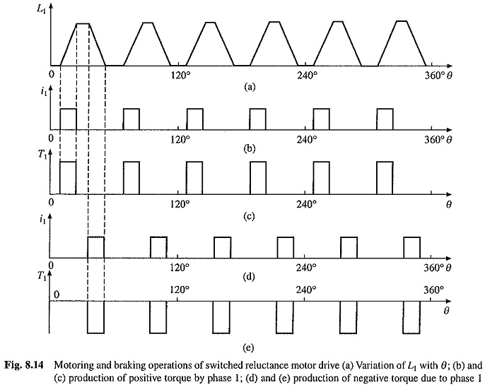
The inductance of a stator phase winding is a function of rotor position due to the saliency of stator and rotor. In the fully-aligned position, the phase winding inductance is maximum and the reluctance of the magnetic circuit is minimum. Similarly in the non-aligned position, the inductance is minimum and reluctance is maximum. Variation of phase 1 winding inductance for various values of θ is shown in Fig. 8.14, where θ is the angle between the reference axis and the axis of rotor pole 1 (Fig. 8.13). Reference axis has been chosen in non-aligned position. Rotor has six poles, therefore, when rotor completes one revolution (i.e. for θ = 0° to 360°), inductance will pass through 6 maximum and 6 minimum values. The angle between the axis of two consecutive rotor poles is 60° and that of stator poles is 45°, hence, if variation of inductance for phase 2 is plotted, it will have similar variation as of phase 1, but displaced by 15° (Fig. 8.13). Therefore, waveforms of phase 3 and 4 will similarly be shifted with respect to phase I waveforms by 30° and 45° respectively.
Consider the phase winding excited by a voltage source of voltage v. Then
where i is the current through the phase winding, R the resistance of the phase winding and ψ the total flux linkage of the phase winding.
Substituting ψ = Li in Eq. (8.2), gives
where ωm = rotor speed in radians/second.
The term ωm i(dL/dθ) is the phase winding back emf e given by the following equation
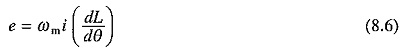
The back emf is a function of i, ωm and (dL/dθ). The instantaneous electrical power input to the machine is given by
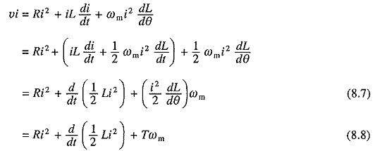
where T is the instantaneous value of developed torque.
The instantaneous power supplied to the machine, vi, is utilized to provide the following:
- winding heat loss, Ri2
- rate of change of the stored magnetic field energy, d/dt (1/2 Li2)
- the mechanical power output
From Eqns. (8.7) and (8.8), the motor torque is given by
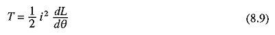
The sign of torque is determined by the slope of L/θ curve and is independent of current direction. If the phase 1 winding is supplied with a pulse of constant current only during periods when dL1/dθ is positive, 6 pulses of positive torque will be produced in one revolution of rotor (Figs. 8.14(b) (c)). If now phases 2, 3 and 4 are also supplied similarly, each phase will be responsible to produce 6 pulses of positive torque each. Therefore, in all 24 positive torque pulses will be acted upon the rotor during one revolution. If the duration of current pulse, and therefore, torque pulse is chosen to be 15°, the rotor will be subjected to continuous torque in the forward direction, giving forward motoring operation (quadrant I). The average motor torque and therefore, motor speed will depend on the amplitude of current pulse. If the motor has been running in the reverse direction, it will provide reverse regenerative braking (quadrant IV) operation.
If the current pulses for each phase are timed to occur when dL/dθ has a negative value (Figs. 8.14(d) (e)), the motor,will be subjected to torque in the backward direction, which can be utilized to obtain reverse motoring (quadrant III) and forward regenerative braking (quadrant II) operation. The ability of the machine to provide four quadrant operation with unidirectional phase currents is an important advantage over ac motors. Because of this feature, the motor can be controlled from a simpler, more reliable and more efficient converter as shown later.
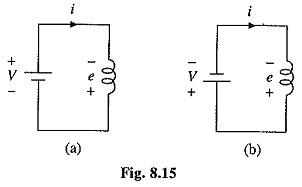
In the above discussion, the machine operation during regenerative braking has been presented from the torque consideration. It is useful to examine it from the energy point of view. For regenerative braking in the forward direction, the winding is excited for rotor angles for which dL/dθ is negative. Because of negative value of dL/dθ, when the winding is excited according to Eq. (8.6), the polarity of the induced voltage e will be as shown in Fig. 8.15(a). Both the dc source and the back emf will supply energy, which will be stored in the winding inductance. Now the source polarity is reversed with respect to the phase winding in order to bring the current to zero. The polarity of motor winding voltage and source and that of the current will be as shown in Fig. 8.15(6). The polarities suggest that the energy stored in the machine inductance and the energy supplied by the machine back emf e will be shifted to the source, providing regeneration.
For identifying the periods for which the phase winding should be excited (periods of positive dL/dθ and negative dL/dθ) for operations in different quadrants, rotor position sensing is required. The rotor position can be sensed either directly from shaft mounted rotor position sensors or indirectly by estimation from phase voltage and currents.
Converter Circuits:
Fig. 8.16 shows two commonly used converters. The bridge converter circuit for one phase is shown in Fig. 8.16(a). A four phase machine will employ four such circuits connected to a common dc source V. It operates in three modes. When both switches Tr1 and Tr2 are closed current flows from the source through the phase winding. When Tr1 is open and Tr2 is closed, the phase current freewheels through the phase winding, D2 and T2. When both switches Tr1 and Tr2 are open, the current flows through feedback diodes D1 and D2 against the source voltage V. The energy stored in the phase winding inductance is returned to the dc source and the current quickly decays to zero. The advantage of this converter is that the current in each phase can be controlled independently. However, the drawback is that it needs two switches per phase.
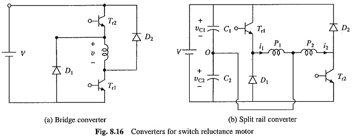
The split rail converter providing control of two phases is shown in Fig. 8.16(b). A four phase machine will require two such converters. When Tr1 is closed, current i1 builds up in phase winding P1, discharging capacitor C1. When Tr1 is opened, phase current i1 charges capacitor C2 through the path P1, C2 and D1 and its value decreases. When Tr2 is closed, current i2 builds up in phase winding P2, discharging capacitor C2. When Tr2 is opened, phase current i2 charges capacitor C1 through the path P2, D2 and C1 and its value falls. The converter has the advantage that only one self-commutated switch is required per phase. It however needs two equal capacitors at the dc bus to split the power supply into positive and negative dc buses, each of voltage V/2 with respect to common bus marked O. In order to apply the same. voltage across the phases, dc link voltage must be doubled and balanced loading must be maintained on capacitors C1 and C2, and therefore, the motor must have even number of phases.
In variable frequency inverter fed induction and synchronous motor drives described in chapters 6 and 7, two self-commutated switches per phase are required. The converter of Fig. 8.16(b) uses only one switch per phase, giving more efficient, cheaper and compact converter.
Modes of Operation:
The source voltage is constant and the back emf increases with speed, the motor phase current waveform and motor behavior are quite different at high and low speeds. At high speeds, while the back emf is large, time duration of torque producing zones (when dL/dθ is either positive Or negative) are small, consequently enough time is not available for current to develop. Fig. 8.17(a) shows the variation of phase current i and flux Φ with rotor position for high speed operation. Since, the phase winding inductance delays the build-up of current, the winding is connected to the dc source earlier than the angle when the inductance begins to rise from its minimum value. The inductance being very small, the current builds up rapidly and reaches a sufficiently large value before the rotor enters the torque-producing zone (when dL/dθ is positive). Subsequently, the rising emf (Eq. (8.6)) causes the current to fall. Since the winding is connected to a constant dc voltage +V, according to Eq. (8.2), the flux Φ increases at a uniform rate. Before the winding inductance reaches the maximum value, the semiconductor switch is turned off at angle θ1. The winding is now subjected to a constant negative voltage —V. The flux decreases at a uniform rate and current falls. Both current and flux fall to zero at an angle θ2. θ1 is chosen to ensure that the current decays to zero before the inductance begins to fall below its maximum value. At high speeds θ0 and θ1 must be chosen very carefully. θ0 is significantly advanced to allow sufficient time for the phase current to build up before the inductance begins to increase. Similarly θ1 is also advanced sufficiently to ensure that the winding current decays to zero before, the rotor reaches the negative torque zone (i.e. when the inductance begins to fall). This mode of operation is called angle control mode. The average torque is controlled by controlling the conduction angle θc (= θ2 — θ0 in Fig. 8.17(a)).
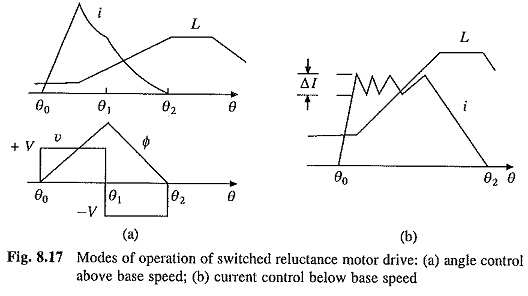
When operating at a low speed, the machine back emf is very small and time duration of phase current is large. Therefore, current will reach very high values. In order to limit the current within safe value and also to obtain rectangular current pulse the semiconductor switch is operated as a chopper with current limit control. The switch is alternately turned on and off in order to make the actual current to follow a reference rectangular current within a hysteresis band Δl (Fig, 8.17(b)). This mode of operation is called current control mode. The average torque in this mode is controlled by controlling the amplitude of current pulse.
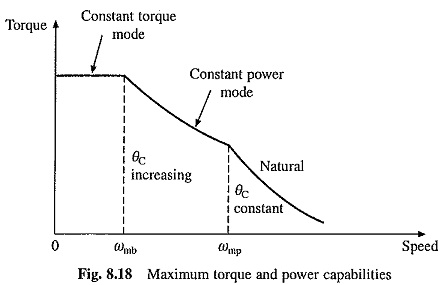
Figure 8.18 gives the modes of operation in terms of maximum torque and power capabilities. The drive operates in current control mode up to base speed ωmb, providing maximum constant torque, thus giving constant torque mode. Above base speed, the drive operates in angle control mode. With a fixed value of conduction angle, torque is proportional to speed squared. By increasing the conduction angle with speed, the drive can be operated in constant power mode. When maximum conduction angle is reached at speed ωmp, the motor operates with its natural characteristics where torque is proportional to speed squared and therefore, maximum available power reduces inversely with speed like a dc series motor.
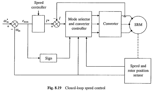
The drive is operated in closed-loop with outer speed loop and inner current control loop, as shown in Fig. 8.19. Depending on the speed, the drive is operated in current control mode or angle control mode. Depending on the sign of speed error the drive is operated in motoring or braking mode.
The Switched Reluctance Motor drives have several advantages, e.g. rugged construction, low maintenance, long life, lower cost of motor and converter compared to all other ac drives, fast response owing to large torque to inertia ratio, simple control, high efficiency, and high reliability. Some disadvantages are torque ripple and high noise, several motors cannot be operated from a single converter and rotor position sensing is required. Although, the Switched Reluctance Motor drives are still at the developmental stage, their applications are projected to grow fast.