Sawtooth Voltage Generator Circuit Diagram and Waveforms:
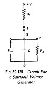
Figure 30.129 represents a basic sawtooth voltage generator. Switch S periodically changes its position from point 1 to point 2 (although a mechanical switch is shown in the circuit, the switching action is actually performed electronically by means of a separate circuit not shown here). The switching action causes the capacitor C to be alternately charged and discharged.
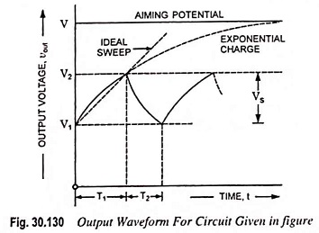
The resulting waveform of output voltage vout is shown in Fig. 30.130. As already explained, the time T1 is called the sweep time and is represented by Ts and time T2 is called the retrace or return time and is represented by Tr. The return or retrace time is required in display systems to return the beam to its original starting point before the next cycle begins.
With the switch S in position 1, the capacitor tends to charge to the supply voltage V, called the aiming potential. Before the capacitor can charge completely, the switch S is brought to position 2, and the capacitor discharges until the switch is returned to position 1, at which time the cycle is repeated. The output voltage is given by
![]()
and
![]()
When t = T1, vout (T1) = V2, so that

and at t = T2, vout (T2) = V1, so that

The sweep amplitude Vs is given as
![]()
The sweep linearity is a measure of how close to the ideal the exponential waveform comes. From Fig. 30.130 it is seen that for smaller values of V2, the straight line and exponential charges are nearly identical. In general, the sweep voltage should be a small fraction of the aiming potential or supply voltage if good linearity is to be achieved.
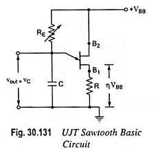
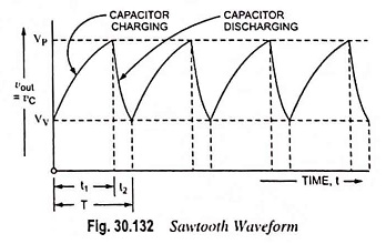
A switching circuit shown in Fig. 30.131 consists of UJT and a capacitor C which is charged through resistor RE when interbase voltage VBB is switched on. During the charging period, the voltage across the capacitor increases exponentially until it attains the peak point voltage VP. When the capacitor voltage attains voltage VP, the UJT switches on and the capacitor C rapidly discharges via B1. The resulting current through the external resistor R develops a voltage spike and the capacitor voltage drops to the value Vv. The device then cuts off and the capacitor commences charging again. The cycle is repeated continually generating a sawtooth waveform across capacitor C. The resulting waveforms of capacitor voltage vC is shown in Fig. 30.132.
The frequency of the output sawtooth wave can he varied by varying the value of resistor RE as it controls the time constant (T = REC) of the capacitor charging circuit. The discharge time t2 is difficult to calculate because the UJT is in its negative resistance region and its resistance is continually changing. However. t2 is normally very much less than t1 and can be neglected for approximation.
For satisfactory operation of the above oscillator, the following two conditions for the turn-on and turn-off of the UJT must be met.

i.e., the range of resistor RE should be as given below

The time period and, therefore, frequency of oscillation can be derived as below.
During charging of capacitor, the voltage across the capacitor is given as
![]()
where REC is the time constant of the capacitor charging circuit and t is the time from the commencement of the charging.
The discharge of the capacitor commences at the end of charging period t1, when the voltage across the capacitor vC becomes equal to VP i.e., (η VBB + VB)
![]()
Neglecting VB in comparison to η VBB we have
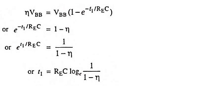
So charging time period,

Since discharging time duration t2 is negligibly small as compared to charging time duration t1, so taking time period of the wave, T = t1
Time period of the sawtooth wave,

and frequency of oscillation

Figure 30.133 shows another circuit for a sawtooth voltage generator. This sawtooth voltage generator circuit uses a four-layer diode as a switch. As soon as the capacitor voltage attains a specified value (10 V in this case), the diode breaks over and the latch closes. This discharges the capacitor, producing the flyback (sudden drop) of the capacitor voltage. At some point on the flyback, the current falls below the holding current, and the four-layer diode opens.
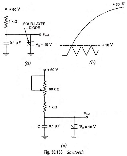
The next cycle then begins. Figure 30.133 (a) is an example of a relaxation oscillator, a circuit whose output depends on the charging and discharging of a capacitor, If RC time constant is increased, then the capacitor takes longer to charge to a specified voltage (10 V in this case) and the frequency of the sawtooth wave decreases. For instance, with the potentiometer shown in Fig. 30.133 (c) we get a 60 : 1 range in frequency.