Induction Generator Transmission Line Diagram:
An induction generator is asynchronous in nature because of which it is commonly used as windmill generator as a windmill runs at non-fixed speed. These are used in remote areas to supplement power received from weak transmission links. A transmission line connected to an induction generator feeding a local load is drawn in Fig. 9.59. The primemover must be provided with automatic control to increase the generator speed when it is required to meet increased load.
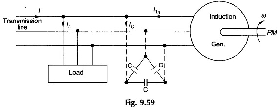
Figure 9.60 shows the circle diagram of an induction machine extended to the generating region i.e., below the OX co-ordinate, which is the negative slip region. At slip = S1g, the motor draws current I1m which lags the applied voltage V1 by Φ1m > 90°. This means negative pf (cos Φ1m) or that the electric power flows out of the machine resulting in generating operation. The generating current fed to the line is then
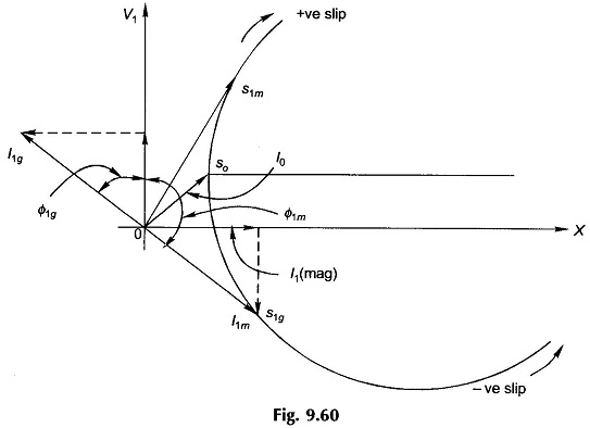
![]()
with a leading pf cos Φ1g. This alternately means that the machine draws a 90°-lagging current component to provide its magnetizing current need. The transmission line has then to feed the lagging current component of the load as well as the magnetizing current of the induction generator. This places a severe lagging VARs load on the already weak lines. This burden must be relieved by connecting balanced shunt capacitors (in delta) across the induction generator terminals. These draw leading current or equivalently feed lagging magnetizing current of the generator.
It is to be observed here that the operating frequency of the system of Fig. 9.59 is fixed by the line frequency.