Constants of a Transmission Line:
A transmission line has resistance, inductance and capacitance uniformly distributed along the whole length of the line. Before we pass on to the methods of finding these Constants of a Transmission Line, it is profitable to understand them thoroughly.
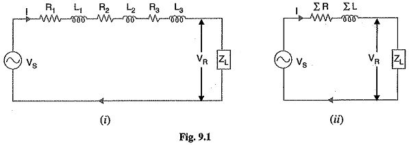
- Resistance: It is the opposition of line conductors to current flow. The resistance is distributed uniformly along the whole length of the line as shown in Fig. 9.1 (i). However, the performance of a transmission line can be analysed conveniently if distributed resistance is considered as lumped as shown in Fig. 9.1(ii).
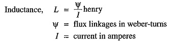
- Inductance: When an alternating current flows through a conductor, a changing flux is set up which links the conductor. Due to these flux linkages, the conductor possesses inductance. Mathematically, inductance is defined as the flux linkages per ampere i.e., The inductance is also uniformly distributed along the length of the line as show in Fig. 9.1(i). Again for the convenience of analysis, it can be taken to be lumped as shown in Fig. 9.1(ii).
- capacitance: We know that any two conductors separated by an insulating material constitute a capacitor. As any two conductors of an overhead transmission line are separated by air which acts as an insulation, therefore, capacitance exists between any two overhead line conductors. The capacitance between the conductors is the charge per unit potential difference i.e.,
![]()
where
q = charge on the line in coulomb
υ = p.d. between the conductors in volts
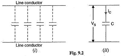
The capacitance is uniformly distributed along the whole length of the line and may be regarded as a uniform series of capacitors connected between the conductors as shown in Fig. 9.2(i). When an alternating voltage is impressed on a transmission line, the charge on the conductors at any point increases and decreases with the increase and decrease of the instantaneous value of the voltage between conductors at that point. The result is that a current (known as charging current) flows between the conductors [See Fig. 9.2(ii)]. This charging current flows in the line even when it is open-circuited i.e., supplying no load. It affects the voltage drop along the line as well as the efficiency and power factor of the line.
Resistance of a Transmission Line:
The resistance of transmission line conductors is the most important cause of power loss in a transmission line. The resistance R of a line conductor having resistivity ρ, length l and area of cross-section a is given by ;
![]()
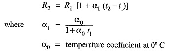
The variation of resistance of metallic conductors with temperature is practically linear over the normal range of operation. Suppose R1 and R2 are the resistances of a conductor at t1°C and t2°C (t2 > t1) respectively. If α1 is the temperature coefficient at t1°C then,
- In a single phase or 2-wire d.c line, the total resistance (known as loop resistance) is equal to double the resistance of either conductor.
- In case of a 3-phase transmission line, resistance per phase is the resistance of one conductor.