Time Base Generator – Working Principle and Types:
Time base is an axis, normally X-axis, that is used to represent time so that variations of quantities such as voltages, currents etc., or their waveforms can be plotted w.r.t. time. Most of the CRO applications involve measurement or display of a quantity which varies with respect to time. This requires that the CRT spot moves across the screen with a constant velocity. For this a voltage which varies linearly with time has to be applied to one set of deflection plates. This voltage is used to sweep the electron beam across the screen, so it is called a sweep voltage. Because of its shape. it is also sometimes called a sawtooth or ramp voltage. The circuits which develop these linearly varying voltages are called time base generator or sweep circuits.
Other applications of time-base circuits are in radar and television indicators, computer monitors, automatic control systems, A/D converters, in precise time measurements and in time modulation.
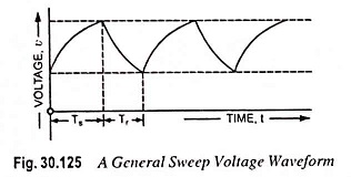
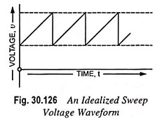
Typical form of a time-base voltage (or sweep voltage) is shown in Fig. 30.125. The voltage starts from some initial value, also may be zero, increases linearly with time to a maximum or peak value, and then returns to its initial value. The time required to return to its value is called restoration time or flyback time (Tr) while the time occupied by the linear portion of the waveform is called sweep time Ts. Sometimes, the shape of the waveform during the restoration or retrace time Tr and restoration time itself are of little significance. However, in some cases it is required that Tr should be very small as compared to Ts. In such a case, when Tr is negligibly small, the waveform will appear as shown in Fig. 30.126. The waveform shown in Fig. 30.126 is an idealized waveform of sweep voltage, where the voltage is exactly linear during the sweep period and the flyback time is zero.
Time base generator do not ordinarily provide sweep voltages that are exactly linear, although every effort is made to obtain reasonable linearity in rise of voltage. Moreover, a linear sweep may get distorted in the course of transmission through a coupling network. The deviation from linearity may be expressed in the following ways.
Slope or sweep speed error es is defined as the ratio of difference in slope at the beginning and end of sweep to the initial value of slope i.e.,
![]()
Such error is significant where constant sweep (rate of change of sweep voltage with time) is an essential requirement as in case of a general purpose CRO.
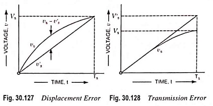
Displacement error, ed is defined as the ratio of maximum difference between the actual sweep voltage and the linear sweep voltage passing through the beginning and end points of the actual sweep to maximum value attained by sweep voltage, as illustrated in Fig. 30.127 i.e.,
![]()
It is used to define nonlinearity of time base signal and is significant in some timing applications.
Transmission error, et is defined as the ratio of the difference between maximum amplitude of input and output signals to the maximum amplitude of signal, as shown in Fig. 30.128 i.e.,
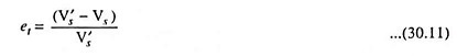
It is caused when a sweep or ramp voltage is passed through a high pass R-C network as in this process maximum amplitude of output falls away from input.
If the deviation from linearity is small, sweep voltage can be approximated by the sum of a linear and a quadratic terms in t, then
![]()
Type of Time Base Generator:
Time base generators may be of two types viz.
- Voltage time-base generators and
- Current time-base generators.
Voltage time-base generators generate a voltage linearly varying with time and are employed where electrostatic deflection is used such as in a CRO. Current time-base generators generate a current linearly varying with time and this current is caused to flow through inductors or deflection coils. Current time-base generators are employed where electromagnetic deflection is used such as in radars, televisions etc. In such applications if electrostatic deflection is used inconveniently large deflection voltages would be required.
Time-base generators may also be classified as triggered free-running and synchronized type. A triggered ramp generator, when triggered by a ramp signal, generates a cycle and then comes back to its stable state. Its pulse rate depends on frequency or pulse repetition rate of applied trigger, the frequency of which may be constant or varying. A free-running time-base generator switches forth and back between two levels and its frequency of oscillation depends on the parameters of the circuit. In a synchronized time-base generator, frequency of oscillation is determined by a clock signal or synchronizing voltage.
All of the above sweep circuits are capable of generating waves of either polarity (i.e., positive or negative).