Steam Turbine Working Principle and Types:
Steam turbines are one of the most versatile and oldest prime movers that transform the potential energy of the steam into kinetic energy and later in turn transformed into mechanical energy – rotation of turbine shaft.
Working principle:
The steam energy is converted into mechanical work by expansion through the turbine. The expansion takes place through a series of fixed blades and moving blades. Each row of fixed blade and moving blade is called stage. The moving blades rotate on the central turbine rotor and fixed blades are concentrically arranged within the circular turbine casing which is designed to withstand the steam pressure.
Types of steam turbine:
Steam turbine can be classified
- According to the design of the moving blade (steam flow) turbine is classified into two types.
- Impulse turbine
- Reaction turbine
- According to the number of pressure stage.
- Single stage turbine
- Multi stage turbine
- According to the direction of steam flow
- Axial turbine
- Radial turbine
Impulse Turbine:
An impulse turbine has fixed nozzles that orient the steam flow into high speed jets due to the expansion of steam in the nozzles. These high speed jet contains significant kinetic energy which is converted into shaft rotation by the moving blades, as the steam jet changes direction. There is a pressure drop at the fixed blades, with net increase in the steam velocity across the stage. The steam leaving the moving blades has maximum velocity. The loss of energy due to this higher exit velocity is called the carry over velocity or leaving loss.
This can be better understood by passing a velocity diagram.
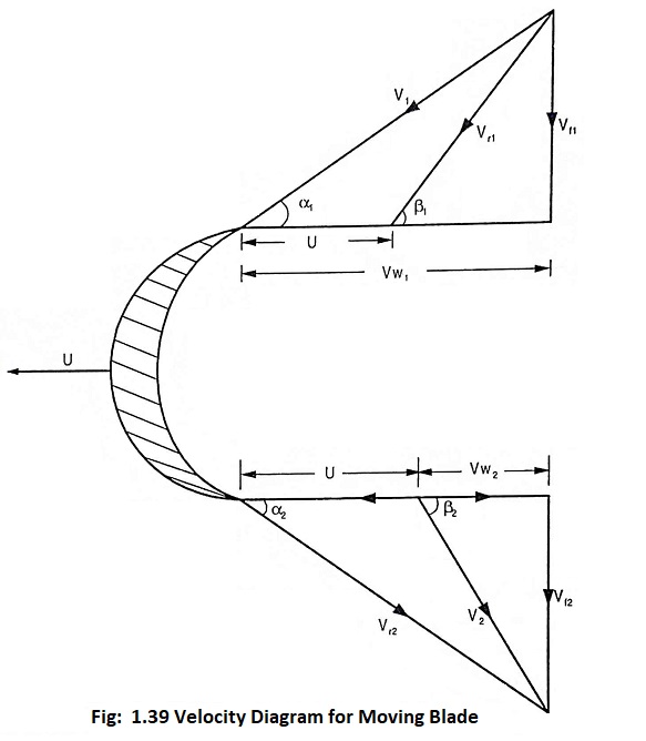
Where
U = Linear velocity of moving blade
V1 and V2 = Absolute velocity of steam at entry and exit respectively
Vw1 and Vw2 = Velocity of whirl at the entry and exit respectively
= Radial component of V1 and V2 respectively
Vf1 = Velocity of flow at entry of moving blade
= axial component of V1
Vf2 = Velocity of flow at exit and moving blade
= Axial component of V2
Vr1 and Vr2 = Relative velocity at entry and exit
α1 = angle with the tangent of the wheel at which the steam enters, also called nozzle angle.
α2 = angle which the discharging steam makes with the tangent of the wheel at the exit.
β1 = Entrance angle of moving blade
β2 = Exit angle of moving blade
The steam jet issuing from the nozzle at a velocity of V1 strikes the blade at an angle α1. Vw1 is the tangential component of the jet which perform work on the blade. The axial component Vf1 does work but causes the steam to flow through the turbine. The blades move with a tangential velocity of U. The entering steam jet has a relative velocity Vr1 which makes an angle β1 with the tangent of wheel. The steam then glides over the blade without any shock and discharges at a relative velocity of Vr2 at an angle β2 with the tangent of blade. The absolute velocity V2 of leaving steam make an angle α2 to the tangent at the wheel.
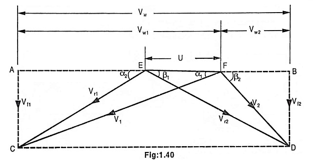
In order to have simplicity while solving problem, it is an usual practice to combine the two vector diagram as shown in Fig. 1.40. The diagram has been obtained by superimposing the inlet velocity diagram on the outlet diagram in order to coincide the blade velocity U.
Work done on blade:
The work done on the blade may be found out by the law of change of momentum of the steam jet during its flow over the blade.
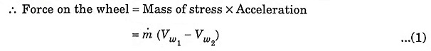
Note:
Vw2 is actually negative as the steam is discharged in the opposite direction to blade motion, therefore consideration should be given to the fact that the values of Vw1 and Vw2 are to be added while solving the problems:
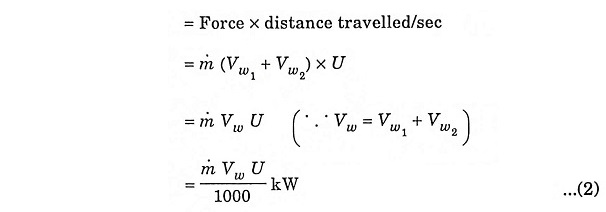
1. Work done on blades/sec
Reaction turbine:
The reaction turbine is turned by reactive force rather than a jerk or impulse in case of impulse turbine. In reaction turbine, there are no nozzles, instead, the blades that project radially from the periphery of the rotor are formed and mounted so that the space between the blades have a shape like nozzle. This blades are mounted on the revolving rotor therefore they are called moving blades.
Fixed blades of the same shape as of the moving blade are fastened to the casing in which the rotor revolves. Fixed blade guides the steam into the moving blades as shown in Fig.1.41.
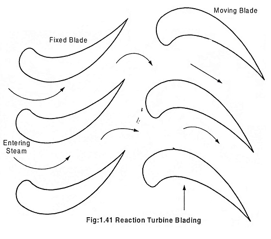
A reaction turbine is moved by three forces
- Reactive force produced on the moving blades as the gas increases in velocity as it expands in the nozzle-shaped spaces between the blades.
- Reactive force produced on the moving blades when the steam changes direction.
- The push of the steam impinging upon the blades.
The reaction turbine which are used now a days are really impulse-reaction turbine as the expansion of steam and heat drop occurs in both fixed and moving blades.
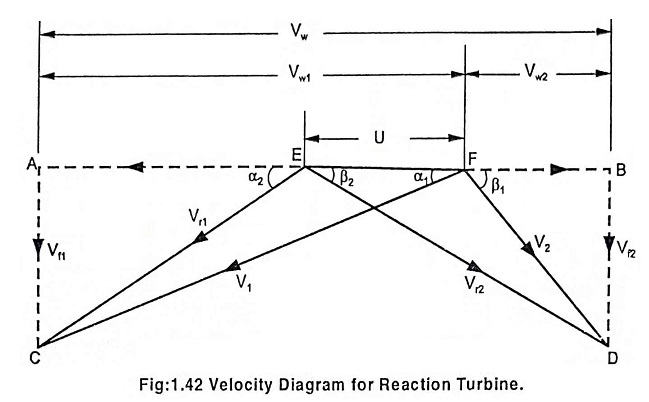
Velocity diagram for reaction turbine blade:
In reaction turbine blades, the steam continuously expands at it flows over the blades. The effect of the continuous expansion of steam during the flow over the blade is to increase the relative velocity of steam.
Note:
Vr2 > Vr1 for reaction turbine
Vr2 ≤ Vr1 for impulse turbine
Degree of reaction:
It is given by the ratio of heat drop over moving blades to the total heat drop in the stage.
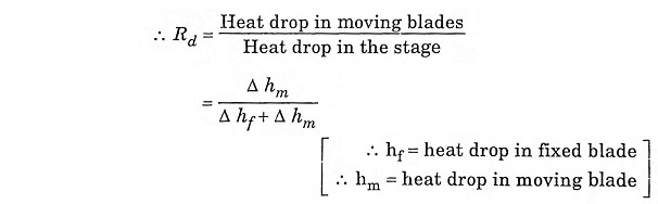
When α1 = β2 and α2 = β1,
the moving blade and fixed blade must have the same shape(symmetrical shape)if the degree of reaction in 50%. This type of turbine is also known as Parson’s reaction turbine.