Resistance Welding – Definition, Working Principle, Types, Advantages and Disadvantages:
Definition – Resistance welding is that process in which a sufficiently strong electric current is sent through the two metal pieces in contact to be welded which melts the metals by the resistance they offer to the flow of the electric current.
Types of Resistance Welding:
Resistance welding includes butt welding, spot welding, projection welding, scam welding and percussion welding. All are alike in the principle of resistance heating but differ in the details of application.
Working Principle:
In resistance welding a heavy current (above 100 A) at a low voltage is passed directly through the workpiece and heat developed by the resistance to the flow of current, given by the expression I2Rt (where I is the current in amperes, R is the resistance in ohms and t is the time or duration of flow of current in seconds) is utilised. The heat developed at the contact area between the pieces to be welded reduces the metal to a plastic state; the pieces are then pressed together to complete the weld. In this process, preferably two copper electrodes are incorporated in a circuit of low resistance and the metals to be welded are pressed between the electrodes. The electrical voltage required ranges from 4 to 12 volts depending on the composition, area, thickness etc. of the metal pieces to be welded. The amount of power supplied to the weld usually ranges from about 60 watts to 180 watts for each sq. mm of area. Alternating current is found to be most suitable for resistance welding as it can provide any desired combination of current and voltage by means of a suitable transformer.
In order to avoid the surface distortion, the portion of the metal adjacent to the weld or joint should not be allowed to be overheated.
Resistance to the flow of current is made of (i) resistance of the current path in the work (ii) resistance between the contact surfaces of the parts being welded and (iii) resistance between the electrodes and the surface of the parts being welded. In order to develop higher temperature between the interfaces of the work to be welded rather than at the surface of the work in contact with the electrodes it is necessary to keep the resistance between the electrodes and the surface of the body being welded to minimum.
In order to obtain a good weld it is necessary to maintain the contact resistance uniform which depends upon the surface condition.
For welding thin materials the resistance of the current path in the work is kept minimum. For welding thick materials of low conductivity the resistance of the current path have a comparatively greater value and the control of contact resistance is not necessary. For welding thick materials of high conductivity either reduced pressure or high resistance electrodes having melting point higher than that of metal to be welded, can be used. For welding two dissimilar metals having different conductivity, low conductivity electrodes on high conductivity metal side and vice versa are used in order to prevent overheating on the low conductivity metal and to develop sufficient heat to melt high conductivity metal side.
The pressure which is to be applied on the weld is also an important factor. At high pressure, low temperature plastic welds can be obtained and where as if the pressure is lowered the resistance to the welding current is to be increased. There is a limit up to which the resistance can be increased and after that there will be surface burning. The pressure necessary to effect the weld varies from 2.5-5.5 kgf/mm2.
The magnitude of current is controlled by varying either the primary voltage of the welding transformer (by using auto—transformer between supply and the welding transformer) or changing the primary turns of the welding transformer. Alternative method of controlling the current to weld is to vary the magnitude and wave of the primary as well as secondary current by using Thyratron or Ignitron tubes in the primary circuit.
In resistance welding, the time for which current flows is very important. Usually automatic arrangements are devised which switch off the supply after a predetermined time from applying of pressure (starting of weld). The pressure may be applied manually, by air pressure, by springs or by hydraulic means. After switching off the supply, the pressure is maintained on the electrodes until the weld cools. In machines which are operated continuously, the electrodes are cooled by water circulating through hollow electrodes.
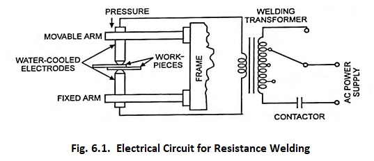
Electrical circuit diagram for resistance welding is shown in Fig. 6.1. The machine employed for resistance welding contains a transformer provided with necessary taps, a clamping device for holding the metal pieces, and a mechanical means for forcing the pieces, to be welded, together to complete the weld.
Resistance welding has the advantage of producing a large volume of work at high speeds that are reproducible with high quality. Resistance welds are made very quickly; however, each process has its own time cycle. Resistance welding operations are automatic. Good-quality welds do not depend on welding operator skill but more on proper set-up and adjustment of the equipment and adherence to weld schedules.
Resistance welding is employed mainly for mass production. It is easily adapted to those components which can be moved to the machine and are light. The operation is extremely rapid and simple. This is the only process where heat can be controlled and which permits a pressure action at the weld. Metals of medium and high resistance, such as steel, stainless steel, monel metal and silicon bronze are easy to weld. Special control gear is required, however, in the case of high-carbon steels and special equipment providing very high current impulses (stored energy welding) is used in case of materials of low electrical resistance.
The automotive industry is the major user followed by the appliance industry. It is used by many industries manufacturing a variety of products made of thinner-gauge metals and for manufacturing pipes, tubing, and smaller structural sections.
When specifying the material intended to he resistance welded, consideration must be given to the state in which this to be supplied to the welding shop. Whilst slight rust, mill scale etc., on the material may not affect the efficiency of arc welds to a considerable degree, lack of cleanliness will be fatal to resistance welded joints. Pickling or shot-blasting immediately prior to the resistance welding operation is essential for making this latter method a success.
Material up to 5 mm thickness which is to be used on resistance-welded jobs is usually purchased in a pickled and slightly oiled condition, and should be carefully stored in order to keep it clean. It can then be used without removing the oil film provided that the oil is clean. Material above 5 mm thickness should be shot-blasted before being taken to the resistance welding machines. No long delay should occur between the shot blasting and the welding, in order to avoid new corrosion which might eliminate the advantage gained by the former. Sandblasting is not recommended, as particles of the siliceous material may be embedded in the steel surface and influence its electrical resistance.
High frequency resistance welding is done with 400 to 450 kHz current usually supplied by an oscillator. The high frequency current readily breaks through oxide film barriers and produces a thin heat-affected zone because it travels on the surface of the material.
Advantages and Disadvantages:
- The initial cost of equipment required is high.
- Skilled persons are required for the maintenance of equipment and its controls.
- In some materials, special surface preparation is required.
- Certain resistance welding processes are limited to lap joints. A lap joint has an inherent device between the two metal pieces, which cause stress concentration in applications where fatigue is present. The device may also cause trouble when corrosion is present.