Electronic Control in Resistance Welding Process:
As there are several factors, i.e., current, pressure, heat, time, to be considered, manual control does not yield good results in case of resistance welding. For the precise control of these factors electronic control in resistance welding circuits are used. Some of the electronic control in resistance welding process circuits are given here.
Ignitron Contactor:
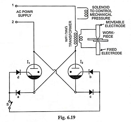
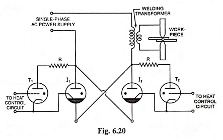
A simple line contactor using two ignitrons is shown in Fig. 6.19. If the switch S is closed at the instant the line 1 is positive, current will rush through the primary of welding transformer, rectifier a, switch S, rectifier b, the ignitron I2 and back to the line 2. The current will strike an arc in ignitron I2 and the tube starts conducting. Now voltage drops across I2 to a low value, causing a voltage drop in the ignitron circuit. Therefore, the ignitron will conduct just long enough to strike an arc. Similarly, during next half cycle, the line 2 will be positive and the current will flow from line 2 through rectifier c, switch S, rectifier d to ignitron I1. During this half cycle, as the anode of ignitron I2 becomes – ve, it stops conducting, Metallic rectifiers are used in this circuit. They conduct the current in proper direction, thus, preventing the application of negative voltages to the electrodes and saving the ignitrons from inverse current damages. A solenoid is used to apply suitable pressure through the upper movable electrode. Manual control of the contactor switch is possible only if the welds are of long duration. But for the accurate time control of the welds of short duration, thyratrons are used to ignite the ignitrons, as shown in Fig. 6.20. The grid circuits of the thyratrons are controlled by a suitable timing control circuit.
Since very heavy current flows through the ignitrons, say 1,000 amperes, and arc drop be taken constant at 10 volts, therefore, losses to the tune of 10 kW will take place. So the ignitrons are always water cooled. In case of very heavy load, temperature of water becomes too high, normally closed thermostat contacts open and the ignitrons stop conducting.
Heat Control Unit:
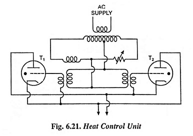
It is an electronic control in resistance welding circuit which helps the delay in the firing of the ignitrons by a definite, predetermined angle in each cycle and operates in conjunction with the line contactor. A typical circuit employed for the heat control is shown in Fig. 6.21. This is essentially a phase shift control circuit and delays the firing of the ignitrons, thus reducing the magnitude of welding current as per requirements.
AC Timer Circuit:
When the condenser C is discharged through a resistor R the voltage across the condenser falls exponentially as given by the expression
From the above expression it is clear that greater the capacity of condenser and value of resistor, greater will be the time required for voltage to fall by given amount. In all timer circuits provision is, therefore, made for charging a condenser to a particular value of voltage and then discharge by short-circuiting switch till condenser is discharged to a particular value when relay will operate and particular contact will open or close.
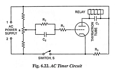
Typical ac timer circuit is shown in Fig. 6.22. Such a timer circuit is used to control the number of cycles for which power may be supplied into the weld. The action of such a timer circuit is explained below.
When switch S is open and supply terminal 1 is positive w.r.t. terminal 2, the cathode and anode of thyratron are at the same potential, and grid is – ve w.r.t. cathode, and, therefore no current flow between cathode and grid. When terminal 1 is negative w.r.t. terminal 2, the potential at a is positive, grid becomes positive w.r.t. cathode and anode and electronic current flows through R2, R1 from grid to cathode, through R3 and to terminal 1. In a few cycles the capacitor C2 will get charged to the maximum voltage between a and 1. This is due to the large value of time constant. The capacitor does not discharge much during the negative half cycle of the grid voltage. Resistance R1 limits the grid-cathode circuit current to a safe value and also determines the number of cycles in which C2 will be fully charged. So long switch S remains open, capacitor C2 remains charged by the grid rectification action. As soon as switch S is closed, the grid becomes very much negative w.r.t. cathode and there is no capacitor charging current through grid rectification. Capacitor will, therefore, start discharging through R2 and -ve bias of the grid will gradually decrease depending upon the time constant R2C2 of the discharge circuit. Conduction in thyratron tube will start during positive half cycle of anode voltage when the grid voltage instantaneously rises to critical grid voltage. Current through relay coil is rectified half waves. As such to avoid relay terminals chatter, a capacitor C1 is connected across relay coil.
Energy Storage Welding Processes:
To meet the demand of heavy current of very high conductivity metals such as aluminium and magnesium energy storage welding circuits are used. There are basically two such circuits namely electrostatically stored energy circuits and electromagnetically stored energy circuits.
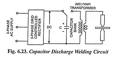
1. Capacitor Discharge Welding Circuit: As shown in Fig. 6.23, condenser C (capacitor bank of capacity of 2,000 to 3,000 μF) is charged to about 3,000 volts from grid controlled rectifier. When the condenser is connected to the primary of welding transformer by ignitron contactor, it will discharge and thus high transient current will be produced in the secondary to weld the material. The noteworthy points in connection with this circuit are :
- As the voltage of condenser approaches the voltage of the source of supply, charging rate becomes lower, therefore to charge condenser to about 3,000 V at high charging rate voltage of about 5,000 V to 6,000 V will be required. A voltage regulating circuit cuts off the rectifier from the bank when the voltage of the bank becomes 3,000 V.
- If there is residual magnetism near saturation, it will result in low rate of change of flux linkages in the secondary and, therefore, in production of low heat. Hence in the welding transformer core flux should not be present.
2. Magnetic Energy Storage Welding Circuit: In this type of welding, energy stored in magnetic circuit is used in the welding operation. The dc voltage of the rectifier is suitably controlled so that the current in the primary of the transformer rises gradually without inducing large current in the secondary. This is necessary to avoid preheating of metals at the weld joint. Preheating in aluminium, magnesium etc. is undesirable as it causes deformation.
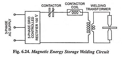
When sufficient energy has been stored up in the transformer core, the contactor opens, dc flow ceases and then-is a rapid collapse of magnetic field. The decay of flux induces heavy currents in the secondary of the transformer for welding.
The kVA demand on the line in magnetic energy storage welding is higher as compared to that in capacitor discharge welding but a high voltage rectifier and costly capacitor bank are not required.