Single Tuned Amplifier – Circuit Operation and Limitations:
The circuit arrangements of a single tuned amplifier are given in Figs. 18.9(a) and 18.9(b). The output may be taken either with the help of a capacitive coupling, as shown in Fig. 18.9(a) or by an inductive coupling as shown in Fig. 18.9(b), R1, R2 and RE form the biasing and stabilization circuits. CE is the bypass capacitor. A parallel tuned L-C circuit connected in the collector circuit, the impedance of which depends upon the frequency, acts as a collector load. Capacitor C is generally variable so that the resonant frequency of the circuit may be varied. Inductor L can also be made variable. If the input signal has the same frequency as the resonant frequency of L-C circuit, large amplification will be obtained because of high impedance of L-C circuit at resonant frequency.
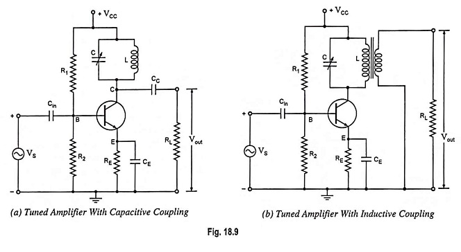
Circuit Operations of Single Tuned Amplifier:
The high frequency signal to be amplified is applied between base and emitter. The resonant frequency of parallel L-C circuit is made equal to the frequency of input signal by varying C (or L). Now the tuned circuit will offer very high impedance to the signal frequency and thus large output will appear across it. In case the input signal is complex consisting of many frequencies, then only the frequency corresponding to the resonant frequency of tuned circuit will be amplified and all other frequencies will be rejected by the tuned circuit. Thus the desired frequency signal is selected and amplified by tuned circuit.
Voltage Gain and Frequency Response Curve:
The voltage gain of an amplifier is given as
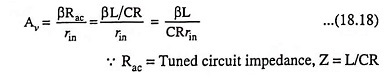
where rin is the input resistance.
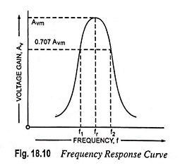
At the resonant frequency, the impedance of the parallel resonant circuit is very high and is purely resistive. Therefore, when the circuit is tuned to resonant frequency, the voltage across RL is maximum. In other words, the voltage gain is maximum at resonant frequency, fr. On both sides of the resonant frequency, the impedance of the tuned circuit decreases, so the voltage. The frequency response curve of a tuned amplifier is shown in Fig. 18.10 which is similar to impedance frequency curve for a parallel resonant circuit. The bandwidth of the single tuned amplifier is given as
![]()
The amplifier will amplify any frequency well within this range.
Limitations:
Tuned voltage amplifiers are usually employed in radio frequency stage of wireless communication systems, where such circuits are assigned the work of selecting the desired carrier frequency and of amplifying the permitted passband around the selected carrier frequency.
In other words, tuned amplifiers are required to be highly selective. But high selectivity requires a tuned circuit with a high Q factor. A high Q circuit will provide a high voltage gain, but at the same time, it will provide much reduced bandwidth because the bandwidth is inversely proportional to the Q factor. It means that a tuned amplifier with reduced bandwidth may not be able to amplify equally the complete band of signals and result in poor reproduction. This is called the potential instability in tuned amplifiers.