What is Resistor in Electronics?
What is Resistor in Electronics? – Resistance is a dissipative element, which converts electrical energy into heat, when the current flows through it in any direction. The process of energy conversion is irreversible.
The circuit element used to represent energy dissipation is most commonly described by requiring the voltage across the element be directly proportional to the current through it. Mathematically, the voltage is
![]()
where i is the current in amperes. The constant of proportionality R is the resistance of the element and is measured in ohms (abbreviated Ω). The voltage-current relation expressed by Eq. (1.1) is known as Ohm’s law. A physical device whose principal electrical characteristic is resistance is known as a resistor.
Since an electric charge gives up energy when passing through a resistor, the voltage v in Eq. (1.1) is a voltage drop in the direction of current. Alternatively, v is a voltage rise in the direction opposite to the current. The conventional diagrammatic representation of a resistance, together with designations of the current direction and voltage polarity, is shown in Fig. 1.2.
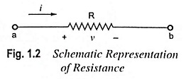
The plus and minus signs denote decrease of potential, and hence a voltage drop, from left to right (or plus to minus). The element has two terminals (also called nodes).
The power dissipated by resistance may be given by expression
Resistor in Electronics are truly ubiquitous. There are almost as many types as there are applications. Resistor in Electronics are employed in amplifiers as loads for active devices, in bias networks, and as feedback elements. In combination with capacitors they establish time constants and act as filters. They are employed for setting operating currents and signal levels. They are employed in power circuits to reduce voltages by dissipating power, to measure currents, and to discharge capacitors after supply is removed. Resistors are employed in precision circuits to establish currents, to provide accurate voltage ratios, and to set precise gain values. In logic circuits they act as bus and line terminators and as “pull-up” and “pull-down” resistors. In high-voltage circuits they are employed for measuring voltages and equalizing leakage currents among diodes or capacitors connected in series. In radio-frequency (RF) circuits they are even employed in coil forms for inductors.
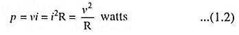
Each Resistor in Electronics has two main characteristics i.e., its resistance value in ohms and its power dissipating capacity in watts. Resistor in Electronics are employed for numerous purposes and as such their resistance values and tolerances and their power ratings vary widely. Resistors are available with resistances from 0.01 Ω through 1012 Ω, standard power ratings from 1/8 watt through 250 W, and accuracies from 0.005% through 20%. Resistors can be made from carbon composition moldings, from metal films, from wire wound on a form, or semiconductor elements similar to field-effect transistors (FETs).
Since no single resistor material or type can be made to encompass all the required ranges and tolerances, many different designs are available. Most common commercially available resistors with their properties are given in Table 1.1.
The value of R is selected to have a desired current I or permissible voltage drop IR. At the same time wattage of the resistor is selected so that it can dissipate the heat losses without getting itself overheated. Too much heat may burn the resistor.
Classification of Resistor:
- Fixed resistors and
- Variable (or adjustable) resistors.
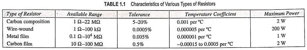
Fixed Resistors: The symbols for fixed resistors used in circuit diagrams are given in Fig. 1.3.
Fixed type resistors are further classified as
- Carbon composition resistors,
- Metalized type and
- Wire-wound type resistors.
Carbon Composition Resistors: This is the most common type of low wattage resistor. The resistive material is of carbon-clay composition and the leads are made of tinned copper. The resistor is enclosed in a plastic case to prevent the entry of moisture and other harmful elements from outside. These Resistor in Electronics have the advantages of being cheap and reliable and their stability is high during their lifetimes, but are highly sensitive to temperature variations. Such resistors are readily available in values ranging from a few ohms to about 22 MΩ having a tolerance range off ± 5 to ± 20%.
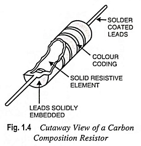
The power dissipating capacity of such units ranges from about 0.1 to 2 watts and the physical size of the larger units have diameters less than 10 mm. The resistors increase in size for increased power ratings in order to withstand the higher currents and dissipation losses. Such resistors have a tendency to develop electric noise due to passage of current from one carbon particle to another and that is why such resistors are used where low cost is the main consideration rather than performance requirements. Such Resistor in Electronics have found widespread use in electronic circuits, although in recent years they are being replaced increasingly by diffused resistors.
The diffused resistors are fabricated by the same procedure as used for integrated circuits (ICs). Such resistors normally carry a tolerance value of ±20% because they cannot be trimmed.
Wire-Wound Resistors: Wire-wound resistors are what their name implies, a length of wire wound around an insulating cylindrical core (Fig. 1.5). Usually wires of materials such as constantan (60% copper, 40% nickel) and manganin which have high resistivities and low temperature coefficients are employed. The completed wire-wound resistor is coated with an insulating material such as baked enamel. As such they are considerably less sensitive to ambient temperature variations. Because the wire’s length, resistivity and size can be carefully controlled, such resistors can be made to be much more accurate than carbon composition resistors. Typical tolerances range from 0.01% up to 1.0%. The range of resistance values of wire-wound resistors varies from approximately 1 Ω to 1 MΩ. They can also be made for high power applications of 5-200 W dissipation ratings (tolerance 5 to 10%). General purpose wire-wound resistors are employed when carbon composition resistors cannot meet either the tolerance, reliability, or power rating specifications of a particular application.
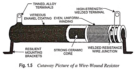
If extremely high accuracy is desired, wire-wound resistors with special alloys are employed for providing long-term stability and low temperature coefficient. Tolerances as low as ± 0.0005% can be had.
The main drawback of wire-wound resistors is the inductance that arises because of their wound, coil-like structures. At high frequencies this often makes the ordinary wire-wound resistor unsuitable. To overcome this problem, a bifilar (dual thread) winding is employed. One-half of the wire is wound in one direction and the other half in the opposite direction. The inductances of the two-halves cancel each other. The resulting resistor is non-inductive but much more expensive than an ordinary wire-wound resistor.
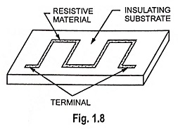
Metal Film and Carbon Film Resistors: The basic structure of carbon film resistor is shown in Fig. 1.6. It is constructed by using film deposition techniques of depositing a thick film of resistive material (pure carbon or some metal) on to an insulating (glass, ceramic or other insulating) substrate in the manner depicted in Fig. 1.8. Only approximate values of resistance can be had by this method. Desired values are obtained by either trimming the layer thickness or by cutting helical grooves of suitable pitch along its length.
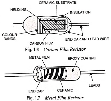
Metal film resistors can range in value up to 10,000 MΩ and are much smaller in size than wire-wound resistors. The problems of inductance and wire size, which limit the values of wire-wound resistors, are thus overcome. The advantages of high accuracy and low temperature coefficient associated with using metal as a resistor material are retained. These attributes, coupled with very low noise, make them best suited for use in low-level amplifiers and computers.
Metal film resistors have excellent tolerance and temperature coefficient and are extremely reliable but are much costlier. They are also sometimes called precision type resistors because they can be had with an accuracy of ±1%. Hence such resistors are very suitable for numerous high grade applications such as in low-level stages of certain instruments.
Carbon film resistors give lower tolerances and smaller values of resistance than those available with metal films. However, the carbon film possesses a mildly negative temperature coefficient which is useful in certain electronic circuits.
Colour Coding of Resistors: Some resistors are large enough in size to have their resistance values and tolerance stamped on their bodies. However, there are small resistors, which are too small in size to have their values printed on them. Hence, a system of colour coding is used.
General Purpose and Precision Colour Codes: Basically, there are two different types of fixed resistors: general purpose and precision resistors. Resistors with tolerance of ±5% or more have four bands or rings and are referred to as general-purpose resistors; resistors with tolerance of ±2% or less are precision resistors and have five bands (or rings).
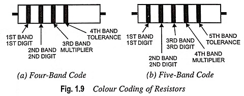
When you pick up a resistor, notice that the bands are nearer one end; this end should be held in your left hand. The colour bands are always read from left to right from the end that has the bands closest to it as illustrated in Fig. 1.9. Four bands on the resistor is an indication of general purpose colour code and five bands of precision colour code.
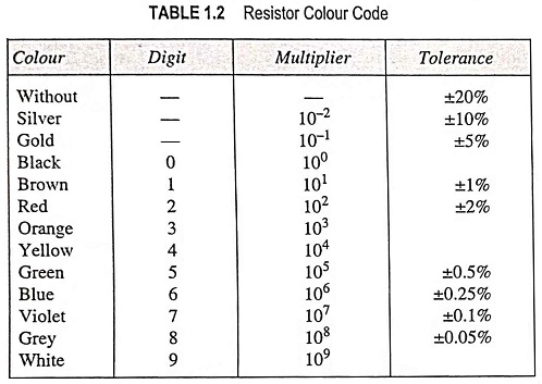
General Purpose Resistor Code: The first and second bands represent the first and second digits, respectively, of the resistance value. The third band indicates the number of zeros that follow the first two digits except that when gold and silver are used. In case the third band is of gold or silver, it represents a multiplying factor of 0.1 and 0.01 respectively. The fourth band represents the tolerance or deviation from the specified resistance value, which is ±5% or more. The noteworthy point is that the first band on either a general-purpose or precision resistor can never be black. The absence of fourth band indicates that the resistor value is within ±20% of the stated value.
For example, a resistor having colour bands of red, green and yellow means the resistance of value 25 x 104 i.e., 250,000 Ω with a tolerance of ±20%; A resistor having a colour bands of yellow, violet, brown and silver means the resistance of value 470 Ω ± 10%.
Precision Resistor Code: The first band, like the general-purpose resistor, is never black and is the first digit of the three-digit number. The second and third bands represent the second and third digits, respectively, of the resistor value. The fourth band specifies the multiplier to be applied to the number. The fifth and last band indicates the tolerance figure of the precision resistor, which is always less than ±2%.
For example, a precision resistor having colour bands of red, orange, green, yellow and blue means the resistance of 235 x 104 Ω with a tolerance of ±0.25%.
General-purpose and precision resistor colour code is given in Table 1.2.
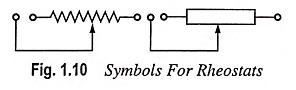
Variable or Adjustable Resistors: For circuits requiring a resistance that can be adjusted while it remains connected in the circuit (such as the volume control on a radio), variable resistors are required. They usually have three leads, two fixed and one movable. If contacts are made to only two leads of the resistor (stationary lead and moving lead), the variable resistor may be used as a rheostat. The symbols for a rheostat are given in Fig. 1.10. Rheostats are usually employed to limit current flowing in circuit branches.
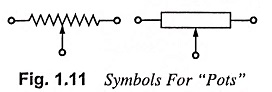
If all the three contacts are employed in a circuit, it is termed a potentiometer or “pot”. Pots are often used as voltage dividers to control or vary voltage across a circuit branch. The symbols for “pots” are given in Fig. 1.11. Thus the potentiometer (or the pot) is a three terminal resistor with an adjustable sliding contact that functions as an adjustable voltage divider and makes it possible to mechanically vary the resistance.
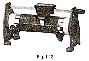
A large laboratory potentiometer (often known as a slide-wire resistor) is shown in Fig. 1.12. Between the inputs at either end, the wire wound around the insulating cylinder provides a fixed resistance. The sliding contact at the top (sometimes controlled by a screw drive and handwheel) allows a variable resistance to be obtained from the element. Two fuses are used to protect the slide-wire pot from inadvertent overload. However, the accuracy of the slide-wire pot is limited by the wire spacing and the fact that the slide can only make contact with the wire along one line of the wire-wound cylinder surface.
For general circuit use, variable resistors are usually made from fixed resistors and a contact capable of rotating on a shaft (Fig. 1.13). The contact is connected to the resistor body in between the fixed terminals. When the shaft is rotated, the third terminal is moved along the resistor; hence, the resistance between it and either of the other terminals varies. Usually, a shaft rotation of 270° moves the sliding contact along the full length of the resistance element. The variation of resistance with shaft rotation is called the taper.
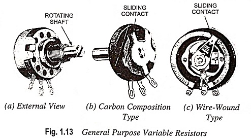
The body of the general purpose variable resistor can be of carbon composition or wire-wound type. The size and rating is specified by giving its total resistance in ohms and the permissible losses in watts. Ranges of 100 Ω to 1 MΩ for the carbon type and 5 Ω to 50 kΩ for the wire-wound type are available. The overall resistance value and the power rating are usually stamped on the unit body.
Precision potentiometers have the feature of being accurate in their variation, if not in their overall resistance value.
Potentiometers are employed for controlling volume in radio-receivers and brightness of pictures in TVs, in instrumentation circuits, process control panels and servo systems in addition to for adjustment and control of pd applied to some device or a part of a circuit.
Special Resistors: Special Resistor in Electronics include LDRs (light dependent resistors), varistors or VDRs (voltage dependent resistors) and thermistors.
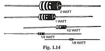
The power rating of a resistor is the maximum power a resistor can handle before burning out.
The maximum power that a carbon composition resistor can handle depends on its size. They are manufactured in 1/8, 1/4, 1/2, 1 and 2 W ratings. Figure 1.14 shows the actual sizes of commercially available carbon composition resistors and their corresponding power ratings.
For applications that require resistors to dissipate more than 2 W, wire-wound resistors are usually chosen. The power ratings of wire-wound resistors are printed directly on the resistors themselves.