Switch Mode Power Supply (SMPS) or Switching Regulators:
Switch Mode Power Supply (SMPS) – The regulated power supplies described earlier were basically linear voltage regulators. A linear voltage regulator possesses many limitations:
- The input transformer is bulky and is a very expensive component in the whole regulated power supply since it is used at low line frequency (50 Hz).
- As the ac frequency is 50 Hz, filter capacitor of large values are required to minimize the ripples introduced.
- The series regulators exhibit 50% efficiency and hence input voltage should be more than output voltage. If efficiency is less, then that part (difference in input and output voltage) of voltage will be dissipated in the form of power in series pass transistor which is always in active region. A TTL system regulator (Vout = 5 V) when operated at 10 V ac input provides 50% efficiency and only 25% for 20 V dc input.
- Another limitation is that in a system with one dc supply voltage (such as +5 V for TTL) if there is need ±15 V for op-amp operation, it may not be economically and practically feasible to achieve this.
Switch mode power supply (SMPS) overcomes the limitations of regulated power supplies. Here in SMPS (or sometimes called switching regulator), the pass transistor is used as a controlled switch and is operated either in cutoff region or saturation region which makes the power transfer via the pass transistor in the form of discrete pulses.
As in the case with other digital switching devices, this mode of operation results in very low power consumption.
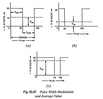
SMPS are used in modem digital equipment such as telephone exchange, PCs, robotics etc., battery powered equipment, video projectors, measuring instruments, space vehicles etc. Such systems need very compact, light weight and highly energy efficient supplies. SMPS utilizes pulse width modulation to control the average value of output voltage. The average value of the waveform depends on the area of waveform. If the TON time (or say, duty cycle TON/TON + TOFF) is varied, the average value of voltage changes proportionately.
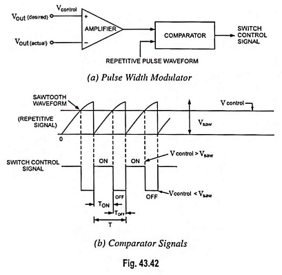
In the PWM switching at constant switching frequency, the switch control signal is generated by comparing Vcontrol and repetitive waveform, as shown in Fig. 43.42.
SMPS or switching regulators can provide large load currents at low voltage precisely what is required in PCs (personal computers).
Switching regulators are available in three basic configurations viz. step-down, step-up and polarity inverting configurations.
Step-down version is shown in Fig. 43.43 (a). The rectangular pulses on the base saturate and cut off the pass transistor during each cycle. This generates a rectangular voltage at the input to LC filter. This filter blocks the ac component and allows the dc component to pass to the output. Because of the on-off switching, the average value is always less than the input voltage. This is why the circuit is called the step-down version.
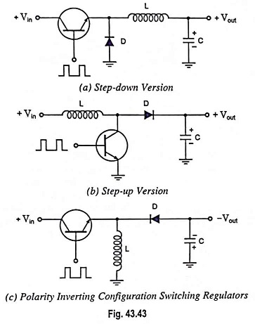
Step-up version of the switching regulator is shown in Fig. 43.43(b). Again, the transistor is alternately saturated and cut off. When the transistor is saturated, current flows through the inductor. When the transistor suddenly cuts off, the magnetic field around the coil collapses and induces a large voltage across the coil of opposite polarity. This keeps the current flowing in the same direction. Furthermore, the inductive kickback voltage is larger than the input voltage. This is why the circuit is called step-up configuration.
Polarity Inverting regulator is shown in Fig. 43.43 (c). When the transistor is saturated, current flows through the inductor. When the transistor cuts off, the magnetic field collapses, and the inductive kickback keeps current flowing in the same direction. Since the transistor is off, the only path is through the capacitor. If the direction of charging current through the capacitor is checked, output voltage is found to be negative.
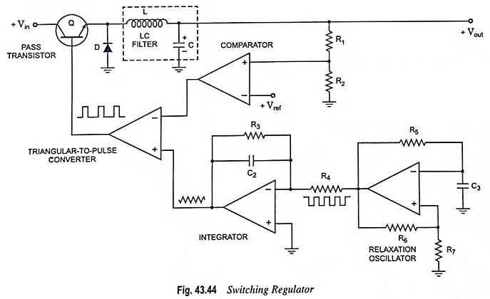
A low-power design, using circuits that we are already familiar with, is illustrated in Fig. 43.44. The relaxation oscillator generates a square wave whose frequency is determined by R5 and C3. The square wave is integrated to provide a triangular wave, which is used to drive the noninverting (+) input of a triangular-to-pulse converter. The pulses out of this circuit then drive the pass transistor. The duty cycle of these pulses will determine the output voltage.
The duty cycle D is the ratio of the on time TON to the time period T. By controlling the duty cycle of the pulse generator, the duty cycle of the input voltage to the LC filter is controlled. The output of the LC filter is a dc voltage with only a small ripple. This output voltage is directly proportional to the duty cycle and is given as
![]()
Since D can vary from 0 to 1, Vout can vary from 0 to Vin.
The output of the LC filter is sampled by a voltage divider, which returns a feedback voltage to the comparator. The feedback voltage is compared with a reference voltage Vref from a zener diode or other source. The output of the comparator then drives the inverting input of the triangular-to-pulse generator.
Operations of Switch Mode Power Supply:
In case the regulated output voltage tends to increase, the comparator provides a higher output voltage, which raises the inverting input voltage to the triangular-to-pulse converter. This narrows the pulses at the base input of the pass transistor. Since the duty cycle is lower, the filtered output voltage is less, which tends to cancel almost all the original increase in the output voltage. It means that any attempted increase in output voltage generates a negative feedback voltage that almost eliminates the original increase. Reverse happens should the output voltage fall.
There is enough open-loop gain in the system to ensure a well-regulated output voltage. Since the error voltage to the comparator is near zero, the voltage across R2 is approximately equal to Vref, So the current through resistor R2 is
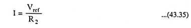
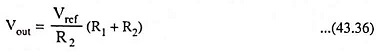
This current flows through R1, which means the output voltage is
Switch Mode Power Supply are available in different circuit configurations including the flyback, feed-forward, push-pull, and non-isolated single-ended or single-polarity types. Also, the switching regulators can operate in any of three modes step-down, step-up, or polarity inverting.
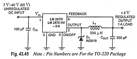
LM 2575 series of regulators developed by National Semiconductor are monolithic ICs that provide the active functions for a step-down (buck) switching regulator, capable of driving a 1 A load with excellent line and load regulation. These devices are available in fixed output voltages of 3.3 V, 5 V, 12 V, 15 V and an adjustable output version.
Requiring a minimum number of external components, these regulators are simple to use and include internal frequency compensation and a fixed-frequency oscillator. LM2575 series offers a high-efficiency replacement for popular 3-terminal linear regulators. It substantially reduces the size of the heat sink, and in many cases no heat sink is required. Fixed output voltage version is illustrated in Fig. 43.45.
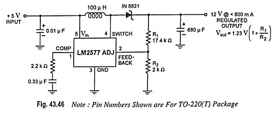
The National Semiconductor LM1577/LM2577 (Fig. 43.46) are monolithic ICs that provide all of the power and control functions for step-up (boost), flyback, and forward converter switching regulators. The device is available in three different output voltage versions: 12 V, 15 V and adjustable.
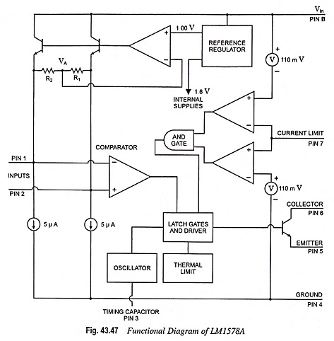
The National Semiconductor LM1578A is a switching regulator which can easily be set up for such dc-to-dc voltage conversion circuits as the buck, boost, and inverting configurations. The LM1578A features a unique comparator input stage which not only has separate pins for both the inverting and noninverting inputs, but also provides an internal 1.0 V reference to each input, thereby simplifying circuit design and PC board layout. The output can switch up to 750 mA and has output pins for its collector and emitter to promote design flexibility. An external current limit terminal may be referenced to either the ground or the Vin terminal, depending upon the application. In addition, the LM1578A has an on board oscillator, which sets the switching frequency with a single external capacitor from < 1 Hz to 100 kHz (typical). It operates from supply voltages of 2 V to 40 V. It is provided with current limit and thermal shutdown. Duty cycle is up to 90 %. Functional diagram is given in Fig. 43.47.
Switch Mode Power Supply have the following advantages over linear regulators:
- High efficiency because of less heat dissipation.
- Light in weight and small in size because of reduced size of transformer.
- Reduced harmonic feedback into the supply mains.
- Isolation from main supply without the requirement of large mains transformer.
- Protection against excessive output voltage by quick acting guard circuits.
- Possibility of conversion of an unregulated input of 24 V into a regulated output of 1,000 V dc.
- Generation of low and medium voltage supplies are easy.
However, they have the following drawbacks :
- Because it operates by switching at high frequency, noise may be troublesome on both the output and the ac input lines (due to induction). Switching regulators throw current transients back into the unregulated supply which are somewhat larger than the maximum load current. Thus, switching need heavy filtering.
- The switching regulator also is limited in its transient response by the switching frequency and is usually considerably slower than a linear regulator (ms versus μs).
- The switching regulator is more complex than linear type. However, this is often a substitution of electrical complexity for the thermal and mechanical complexity of high power linear regulators.
- Though RF interference can be a problem in SMPS unless properly shielded. SMPS in TV sets is in synchronization with the line frequency (15,625 kHz) and thus switching effects are not visible on screen.
For above reasons, the use of switching regulators is usually limited to power levels around 100 W.