Constant Voltage Transformer (CVT) – Construction and Working Principle:
With the popularization of PCs, the constant voltage transformers (CVTs) have also become equally popular. The Constant Voltage Transformer is simply a magnetic transformer of a special construction that has a capacitor connected across the secondary winding of the transformer.
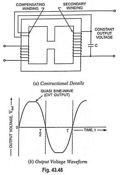
In an ordinary transformer, the primary and secondary windings are wound near each other so that whenever there is a change of voltage across the primary there is a corresponding change in the secondary voltage depending upon the ratio of the turns on the two windings. However, in a Constant Voltage Transformer the primary and secondary windings are wound separately from each other, as illustrated in Fig. 43.48(a). To set up field in between the coils, a separate shunt path is provided between the two windings but an airgap is formed in the shunt path. A capacitor is connected across suitable tappings of the secondary winding. The constructional details of a CVT are shown in Fig. 43.48(a).
Operation of CVT:
The portion of the magnetic core over which the secondary winding is wound is saturated, while the portion over which the primary is wound is not saturated. A capacitor is connected across the secondary winding to tune out the output at a frequency very close to 50 Hz. This capacitor also makes the current in the secondary winding to increase which helps in the saturation of the secondary flux. Since the secondary ac flux is restricted to a saturated value for a large range of the input voltage (170-270 V), a constant voltage is available across the secondary winding. The output voltage will not be of a pure sinusoidal waveform but will be an approximate sinewave with the peaks flattened approaching a square wave. Output voltage waveform of a CVT is shown in Fig. 43.48(b). In Fig. 43.48(a), a compensating winding is shown connected in series to the secondary to improve the CVT performance.
If a Constant Voltage Transformer is placed at the output of a square wave inverter (in the UPS), care must be taken to control the frequency of the inverter, since the CVT is sensitive to the frequency of its input supply.
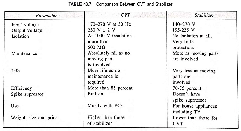
The reason we use a CVT and not a voltage stabilizer for computer applications is that in the voltage stabilizer relays are present and when these relays operate (switch), the output voltage may be interrupted for a short time. Such a transient may not be desirable for computers which may cause the computer to reboot. Also, the CVT provides a clean spike-free output voltage. The voltage regulation possible in a CVT also is good. The comparison between a Constant Voltage Transformer and a stabilizer is shown in Table 43.7.
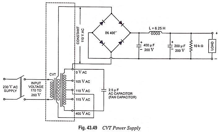
The input voltage ranges 170 to 260 V and output regulation is 230 ± 2 % at no load to full-load. Distortion-approximately 5 % under full-load conditions. Rating of 50, 150, 250, 350, 500, 750, 1000, 2000 VA.
A practical circuit of a Constant Voltage Transformer power supply is given in Fig. 43.49.