Construction and Working Principle of DC Motor:
Construction and Working Principle of DC Motor is a heteropolar structure with stationary poles and the rotating armature (Fig. 5.8).
DC Machine Basic Structure:
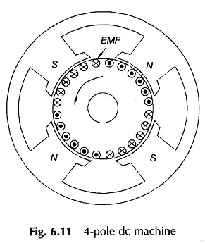
An alternating emf of the same wave shape as that of B-wave is induced in every coil. As the armature rotates, the emf s induced in the belt of coil-sides under a given pole is unidirectional and the pattern alternates from pole to pole as shown in Fig. 6.11 for a 4-pole DC Machine. For obtaining a constant voltage from armature coils, rectification action is required. This can be achieved by the mechanical rectifier—commutator and brushes.
Construction of DC Machine:
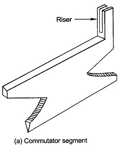
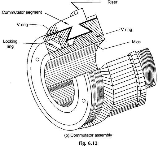
The commutator is a cylindrical assembly of wedge-shaped copper segments (Fig. 6.12(a)) insulated from one another and the shaft by thin mica or micanite sheets. In high-speed Construction and Working Principle of DC Motor, the segments are so shaped that they can be clamped by two cast-iron V-shaped rings as shown in Fig. 6.12(b). Each commutator segment forms the junction between two armature coils (“finish” of one coil and “start” of the other). In large machines flat copper strips known as risers are used forming clip connections to armature bar conductors (Fig. 6.12(b)).
A double-layer winding is universally adopted in Construction and Working of DC Machine. The coils are continuously connected “finish” to “start” to form a closed (re-entrant) winding. Depending upon the type of connection (lap or wave), pairs (one or more) of parallel paths exist. Points of maximum voltage (corresponding to a path) are tapped by means of stationary brushes placed on the commutator. As the armature rotates, the number of series coils tapped remains fixed and their relative disposition with respect to poles does not change. Therefore, constant (dc) voltage appears across the brush pair.
Working Principle of DC Machine:
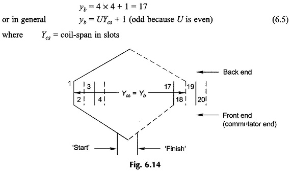
Coil-sides are numbered continuously—top, bottom, top, . . . The first top coil-side is numbered 1 so that all top ones are odd and all bottom ones even. Figure 6.13 shows the coil-side numbering scheme for U=4 coil-sides/slot.
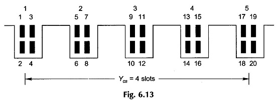
In Fig. 6.13 the coil-span Ycs is assumed 4 slots (or the coil spans 4 teeth). Therefore, coil-side 1 will form a coil with coil-side 18 and 3 with 20, and so on. This is depicted in Fig. 6.14. The coil-span in terms of coil-sides is Ycs = 18 – 1 = 17 or 20 – 3 = 17. This indeed is the distance measured in coil-sides between two coil-sides connected at the back end of armature (end away from commutator) to form a coil. It is known as back-pitch denoted as yb. Obviously coil-span
![]()
which is odd in this case and must always be so. It indeed equals
Commutation in DC Machine:
The junction of two coils (“finish” – “start”) is connected to one commutator segment.
Therefore,
Number of commutator segments = C (number of armature coils) (6.6)
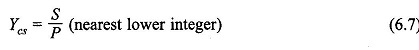
The number of commutator segments spanned by the two ends of a coil is called commutator-pitch, yc. In Fig. 6.15 (a), yc = 2 – 1 = +1.
Coil-Span:
The coil-span in terms of slots is always nearly full-pitch. This ensures that coil-side voltages around the coil are additive most of the time (except when coil-sides lie near the magnetic neutral region). Thus
which means that for nonintegral S/P, the coils are short-pitched.
Lap Winding:
In a lap winding (as in case of ac) the “finish” of one coil (coming from the bottom coil-side) is connected to (lapped on) the “start” of the adjoining coil as illustrated for single-turn coils in Fig. 6.15(a). The coil-side displacement of the front end connection is called the front-pitch, yf. In a lap winding the resultant-pitch
The direction in which the winding progresses depends upon which is more, yb or yf. Thus
yb> yf (Progressive winding, Fig. 6.15(a)) (6.9a)
yb < yf (Retrogressive winding, Fig. 6.15(b)) (6.9b)
There is not much to choose between progressive or retrogressive winding; either could be adopted.
As shown in Figs. 6.15 (a) and (b), the two ends of a coil are connected across adjacent commutator segments. Thus commutator-pitch,
yc = ± 1 (±1 for progressive, –1 for retrogressive) (6.10)
Coils in lap winding are continuously connected as per the above rule and in the end it closes onto itself (as it must). In the process all coils have been connected.
To learn certain further aspects of lap winding—location of brushes, etc., an example is worked out.
EMF Equation of DC Generator:
The three coils (C/P = 12/4) shown in a thick line are located under one pole-pair (N1S1) and are series connected so that their emf’s add up. This constitutes one parallel path. The complete winding can be divided into four such parallel paths lying under four different pole-pairs (N1S1, S1N2, N2S2, S2N1). It is, therefore, concluded that the number of parallel paths (A) in a lap-wound Construction and Working Principle of DC Motor in general equal the number of poles (P), i.e.
A = P (6.11)
The four parallel paths in the winding of Fig. 6.16 electrically form a close ring as shown in Fig. 6.17 in which the parallel path emf’s around the loop alternate.
DC Machine Equivalent Circuit:
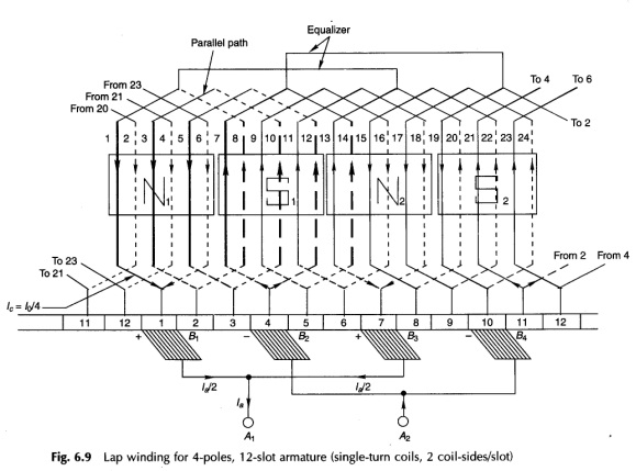

The ends of parallel paths meet at commutator segments 1, 4, 7 and 10 at the instant shown. These are the locations of the brushes (equal to the number of poles) and are alternately positive and negative. It is also found that the brushes are physically located opposite the pole centres and the electrical angle between them is, therefore, 180°. The spacing between adjacent brushes in terms of the commutator segment is
It may also be noted that C/P need not necessarily be an integer. It is further noticed that because of the diamond shape of coils, the brushes which are physically opposite the pole centres are electrically connected to coil-sides lying close to the interpolar region. Thus electrically the brushes are displaced 90° elect. from the axes of the main poles.
The two positive and two negative brushes are respectively connected in parallel for feeding the external circuit.
From the ring diagram of Fig. 6.17, which corresponds to the winding diagram of Fig. 6.16, it immediately follows that the current in armature conductors is
Commutation:
Consider any parallel path, say the one drawn in a thick line in Fig. 6.16, tapped at commutator segments 1 and 4. As the armature rotates, one coil moves out of this parallel path at one brush and another coil enters the parallel path at the other brush. The brush pair now taps commutator segments 2 and 5. This process happens simultaneously at all the brushes and can be more easily imagined from the ring diagram of Fig. 6.17 wherein the coils can be considered to rotate in a circular fashion. In this way a brush pair always taps C/P coils (in series) and as a consequence the voltage available at each brush pair is maintained constant (dc). This indeed is the commutation action. As a matter of fact the voltage tapped varies slightly for a brief period when the changeover of coils in parallel paths takes place. However, this voltage variation is negligible in practical Construction and Working Principle of DC Motor which have a large number of coils.
It easily follows from the winding diagram of Fig. 6.16 and from the equivalent ring diagram of Fig. 6.17 that as a coil moves out of one parallel path into another, the current in it must reverse. In Fig. 6.16 as the armature moves by one commutator segment, currents in four coils—(1, 8), (7, 14), (13, 20) and (19, 2)—must reverse. These coils are said to undergo current commutation. It is also observed that during the brief period in which a coil undergoes commutation, its coil-sides are passing through the interpolar region so that negligible emf is induced in the commutating coil. At the same time, in this period the coil remains short-circuited by the brush, bridging the adjoining commutator segments to which the coil ends are connected. If the current in a coil does not reverse fully at the end of commutation period, there will be sparking at the brush contact.
Symmetry Requirement:
To avoid no-load circulating currents and certain consequential commutation problems, all the parallel paths must be identical so as to have the same number of coil-sides. Symmetry therefore requires that
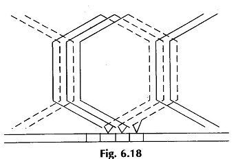
To practically wind a dc the coils of the double-layer rules are not needed except that winding are to be continuously connected from “finish” to “start” till the winding closes onto itself. Further the “finish-start” junction is connected to armature the above winding the commutator segment physically opposite the midpoint of the coil; the ends of each coil being connected to the adjacent commutator segment. This is illustrated in Fig. 6.18. Of course the winding rules given above help in providing an insight to the reader into the winding and commutator action to produce dc at the brushes.
Equalizer Rings:
The poles in a Construction and Working Principle of DC Motor cannot be made identical so as to have the same value of flux/pole. Any dissymmetry among poles leads to inequality in parallel path emf s e.g. in Fig. 6.17, E1(N1S1), E2(S1N2), E3(N2S2) and E4(S2N1) will not be identical. As a result the potential of the positive and negative brush sets are no longer equal so that circulating current will flow in the armature via the brushes to equalize the brush voltage even when the armature is not feeding current to the external circuit. Apart from causing unbalanced loading around the armature periphery when the armature feeds current, the circulating currents also interfere with “commutation” resulting in serious sparking at the brushes.
The circulating currents even out pole dissymmetry by strengthening the weak poles and by weakening the strong poles. The remedy is therefore to allow the circulating currents to flow at the back end of the armature via low resistance paths inhibiting thereby the flow of these currents through carbon brushes which in comparison have considerably higher resistance. This remedy is applied by connecting several sets of points which would be “equipotential” but for the imbalance of field poles via equalizer rings. Currents flowing in the rings would of course be ac as only ac voltage exists between points on coil back ends. Equipotential points are 360° (elect.) apart and would be found only if![]()
i.e. winding exactly repeats for each pair of poles. The distance between equipotential points in terms of number of commutator segments is C/(P/2), i.e. 12/2 = 6 in the example. It is too expensive to use equalizer rings equal to the number of equipotential point-pairs; a much smaller number is employed in actual practice. Two equalizer rings are shown properly connected in Fig. 6.16 for the example.
While equalizer rings inhibit the flow of circulating currents via brushes, they are not a prevention for the circulating currents which do cause additional copper losses.
It will soon be seen that wave winding scheme does not have the need of equalizer rings and would naturally be preferred except in large heavy current Construction and Working Principle of DC Motor.
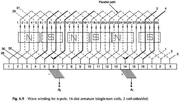
Wave Winding:
In wave winding the “finish” end of one coil under one pole-pair is connected to the start of a coil under the next pole-pair as shown in Fig. 6.19. The process is continued till all the armature coils are connected and the winding closes onto itself. Certain conditions must be fulfilled for this to happen. The winding has the appearance of a wave and hence the name. The ends of each coil spread outwards and span y, (commutator pitch) segments. As the number of coil-sides is double the number of segments, the top coil-side of the second coil will be numbered (1 + 2yc).
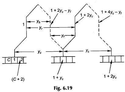
Starting at segment 1 and after going through P/2 coils or yc(P/2) segments, the winding should end up in segment 2 for progressive winding or segment (C) for retrogressive winding. This means that for the winding to continue and cover all the coils before closing onto itself, i.e.
Once yb is known from the coil-span and yc is determined from Eq. (6.16), the back-pitch yf is calculated from Eq. (6.15). The winding diagram can now be drawn.
In wave winding the coils are divided into two groups—all coils with clockwise current are series connected and so are all coils with counter-clockwise current—and these two groups are in parallel because the winding is closed. Thus a wave winding has always two parallel paths irrespective of the number of poles; also only two brushes are required, i.e.
A = 2 (6.17)
As per the above values of various pitches, the developed diagram of the winding is drawn in Fig. 6.20. It is observed that the armature winding has two parallel paths (one of the parallel paths is shown thick in Fig. 6.20)—current is going in at segment 6 and is coming out at segment 14 (coil-side 27 has negligible emf and the direction of current in it is determined by the next coil-side in series with it, i.e. 32). Only two brushes are, therefore required—one brush is opposite a north pole and the other opposite the diametrically opposite south pole. The spacing between brushes is
![]()
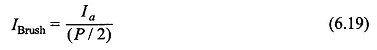
In practical wave-wound DC Machine as many brushes as number of poles are used with spacing between adjacent brushes being C/P commutator segments and the brushes are alternatively positive and negative. All positive and all negative brushes are respectively connected in parallel to feed the external circuit. This reduces the current to be carried by each brush to a value.
For a given commutator segment width this reduces the segment length required for maximum allowable brush current density. In small machines, however economy cost of brush gear relative to commutator dictates in favour of two brushes only, which are placed opposite two adjoining poles.
Equalizer rings not needed:
The armature coils forming each of the two parallel paths are under the influence of all pole-pairs so that the effect of the magnetic circuit asymmetry is equally present in both the parallel paths resulting in equal parallel-path voltages. Thus equalizer rings are not needed in a wave winding.
Dummy coils:
In a lap winding yc = ±1 irrespective of the number of armature coils so that coils can always be chosen to completely fill all the slots (C = 1/2 US).
In a wave winding from Eq. (6.16), the number of coils must fulfil the condition
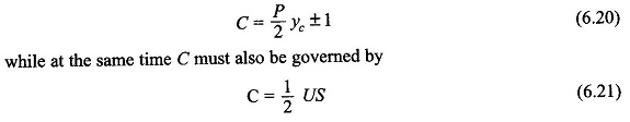
C = P/2 yc ± 1 (6.20)
while at the same time C must also be governed by
For a certain-design value of P and the choice of S restricted by manufacturing considerations (availability of a certain notching gear for armature stamping), the values of C as obtained from Eqs (6.20) and (6.21) may not be the same. In such a situation the number of coils C’ is dictated by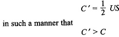
and yc is so selected that (C’ — C) is the least possible. Electrically only C coils (Eq. (6.20)) are needed, but C’ coils are accommodated in the armature slots to ensure dynamic (mechanical) balancing of the armature. The difference (C ‘ — C) are called dummy coils and are placed in appropriate slots with their ends electrically insulated.
As an example, if P = 4n (multiple of four), C can only be odd (Eq. (6.20)), while C’ may be even if an even number of slots are used. In this case then at least one dummy coil would be needed.