Hybrid Parameters of Transistor or h Parameters and Hybrid Model:
A box representing a two-port network is illustrated in Fig. 11.1. The terminal behavior of a two-port device may be specified by two voltages and two currents (voltage v1, and current ii at the input port and voltage v2 and current i2 at the output port). The conventional positive polarities of voltages v1 and v2 and currents i1 and i2 are shown in the figure. Out of four quantities (v1, v2, i1 and i2), any two may be selected as independent variables and the remaining two be expressed in terms of the selected independent variables. This leads to various two-port parameters, out of which following three are more important.
- Open-circuit impedance parameters or Z-parameters Z11, Z12, Z21 and Z22
- Short-circuit admittance parameters or Y-parameters Y11, Y12, Y21 and Y22
- Hybrid parameters or the h parameters.
In transistor amplifier analysis, Z- and Y-parameters were used earlier. But now Hybrid Parameters of Transistor or the h parameters alone are used in a transistor circuit analysis and, therefore, only the h parameters will be taken here for discussion.
Hybrid Parameters of Transistor or h Parameters:
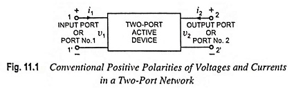
For the two-port network illustrated in Fig. 11.1, if input current i1 and the output voltage v2 are taken as independent variables and the two-port shown in the figure is linear, we may write
![]()
In the above equations, the hs are fixed for a given circuit and are called the Hybrid Parameters of Transistor or h parameters. Because these four parameters have mixed dimensions (h11 has dimension of ohm, h12 and h21 are dimensionless, and h22 has dimension of mho or siemen) so they are called Hybrid Parameters of Transistor or h parameters.
1. Meaning of h Parameters: By assuming that the given two-port network has no reactive element and by applying open circuit (i1 = 0) or short circuit (v2 = 0) conditions to Eqs. (11.1) and (11.2), the h parameters can be defined as below :
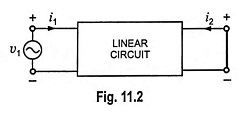
If the output terminals are short circuited, (Fig. 11.2) output voltage v2 becomes zero and Eqs. (11.1) and (11.2) become
![]()
![]()
Since h11 is the ratio of input voltage and input current with output terminals short circuited, it is called the input impedance with output short circuited. The subscript 11 of h11 defines the fact that the parameter is determined by the ratio of quantities measured at the input terminals. Its unit is ohm.
Similarly h21 is the ratio of output and input currents (i.e. i2/i1) with output terminals short circuited, so it is called the forward transfer current gain with output short circuited. Obviously it is dimensionless quantity.
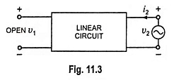
If the input terminals are open circuited and we drive the output terminals with voltage v2, as shown in Fig. 11.3, input current i1 becomes zero and Eqs. (11.1) and (11.2) become
![]()
![]()
Thus the parameter h12 is the ratio of input voltage to the output voltage with zero input current (i.e. i1 = 0). It is dimensionless quantity and is called the open-circuit reverse transfer voltage ratio, the subscript 12 of h12 reveals that the parameter is a transfer quantity determined by the ratio of input to output measurements.
Similarly h22 is the ratio of output current to the output voltage with zero input current (i.e. i1 = 0). It is called the open-circuit output admittance and is measured in siemens. The subscript 22 in h22 indicates that it is determined by a ratio of output quantities.
2. Notations: The convenient alternative subscript notations recommended by the IEEE Standards are given below:
![]()
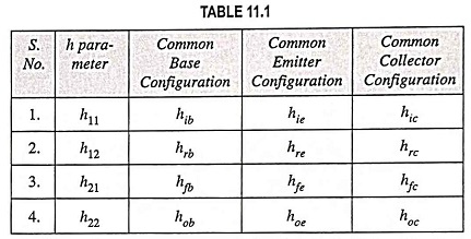
In case of transistors, another subscript (b, e or c) is added to designate the type of transistor configuration. For example hie = h11e = input resistance in common-emitter configuration.
Notations used in transistor amplifier for the three configurations are tabulated in Table 11.1.
Since the two-port network (or the device) described by Eqs. (11.1) and (11.2) is assumed to have no reactive elements, the four parameters h11, h12, h21 and h22 are real numbers and voltages and currents v1, v2, and i1, i2 are functions of time. However, if the reactive elements had been included in the device, the excitation would be considered to be sinusoidal, the h parameters would in general be functions of frequency, and the voltages and currents would be represented by phasors V1, V2, and I1, I2.
Hybrid Model:
The hybrid circuit for any two-port network characterized by Eqs.(11.1) and (11.2) is shown in Fig. 11.4. If Kirchhoff s voltage law and Kirchhoff’s current law are applied to the input and output ports, Eqs. (11.1) and (11.2) respectively will be obtained. Thus model given in Fig. 11.4 truely satisfies Eqs. (11.1) and (11.2).
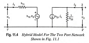
The input circuit derived from Eq. (11.1) appears as a resistance h11 in series with a voltage generator h12v2. The output circuit, derived from Eq. (11.2) consists of a current generator h21i1 and shunt resistance 1/h22. This circuit is called hybrid equivalent because its input portion is a Thevenin’s equivalent (or a voltage generator in series with a resistance) while the output portion is a Norton’s equivalent (or a current generator with shunt resistance). Thus it is a mixture or hybrid. The symbol ‘h’ is simply the abbreviation of the word hybrid (hybrid means “mixed”).
The hybrid equivalent circuit (or model) given in Fig. 11.4 is an extremely important one in the area of electronics today. It will appear over and over again in the analysis to follow. There are two main reasons of popularity of hybrid model. First, it isolates the input and output circuits, their interaction being accounted for by the two controlled voltage and current sources—the effect of output upon input is represented by the equivalent voltage generator h12v2 and the effect of input upon output is represented by the current generator h21i1. The value of the former depends upon the output voltage v2 while the value for the latter depends upon the input current i1. Secondly, the two portions of the circuit are in a form which makes it simple to take into account the source and the load circuits.