Square Law Diode Modulator – Circuit Diagram and its V-I Characteristics:
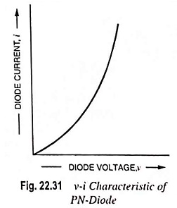
Basic circuit of a square law diode modulator is shown in Fig. 22.30. It utilizes the nonlinear region of voltage-current dynamic characteristic of a P-N diode. This square law diode modulator method is suited at low voltage levels because of the fact that current-voltage characteristic of a diode is highly nonlinear, particularly in the low voltage region, as shown in Fig. 22.31.
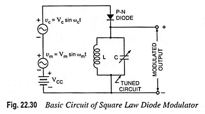
As shown in Fig. 22.30, carrier and modulating signals are simultaneously applied across the diode. DC supply VCC is connected across the diode to provide a fixed operating point on the v-i characteristic of diode. The square law diode modulator operates on the principle that when two different frequencies are simultaneously passed through a nonlinear device, such as diode, the process of amplitude modulation occurs. Hence, when carrier and modulating frequencies are simultaneously applied at the input of diode, then different frequency terms appear at the output of diode. These different frequency terms are applied across a tuned circuit which is tuned to the carrier frequency and has a narrow bandwidth just to pass two sidebands along with the carrier and reject other frequencies. Thus, at the output of the tuned circuit, carrier and two sidebands are obtained i.e., generation of AM wave.
The ac current i may be expressed as a function of ac voltage vs as given by the following Taylor series.
![]()
where a1 and a2 are the Taylor series coefficients
![]()
Substituting the value of vs from Eq. (22.35) in Eq. (22.34), we have

The quantity in bracket derives from the square term in Eq. (22.34). A little thought reveals that it is this term which gives rise to the product of the carrier and modulating sinusoids, which, in turn, yields the upper and lower frequency sidebands thereby permitting the amplitude modulated signal to be identified.
Substituting

in above equation we have
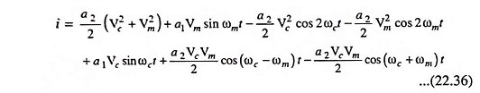
The last three terms of Eq. (22.36) are identical in form to those appearing in Eq. (22.15), so that together they yield in the output tuned circuit the desired amplitude modulated signal. The first four terms are of no use and can be filtered out by tuning L-C circuit to frequency ωc. The output current is given as
![]()