Simple Slope Detector – Circuit diagram and its Characteristics:
The circuit diagram of a simple slope detector is depicted in Fig. 22.52(a). This Slope Detector circuit consists of a tuned circuit which is slightly detuned from the carrier frequency ωc. In other words, the circuit uses two tuned circuits which are tuned to two different frequencies. First one is tuned to the incoming FM carrier frequency ωc whereas the second is tuned to a frequency slightly different from the carrier frequency ωc. Thus, this portion of circuit which contains two tuned circuits tuned to different frequencies, is called discriminator.
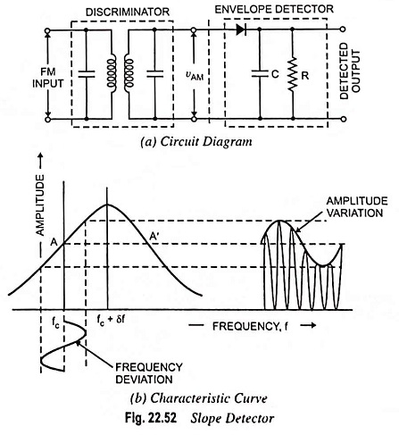
This circuit converts FM signal into an AM signal as shown in the slope detector characteristic curve. The another portion of the circuit is envelope detector. The AM signal from the output of the discriminator is applied at the input of the envelope detector. At the output of the envelope detector, the original modulating signal is obtained.
No doubt, this circuit is simple and inexpensive but it has following shortcomings:
- The circuit’s nonlinear characteristic produces a harmonic distortion. The nonlinearity is obvious from the fact that the slope is not the same at each point of the characteristics.
- The circuit does not eliminate the amplitude variations and the output is sensitive to any amplitude variations in the input FM signal which is obviously not a desirable feature. A good discriminator circuit must respond only to frequency variations and not to amplitude variations.
- It is less efficient.