Slope Detector FM Demodulation:
Consider a frequency-modulated signal fed to a tuned circuit whose resonant frequency is to one side of the center frequency of the FM signal. The output of this tuned circuit will have an amplitude that depends on the frequency deviation of the input signal; Slope Detector FM Demodulation that is illustrated in Figure 6-33. As shown, the circuit is detuned by an amount δf, to bring the carrier center frequency to point A on the selectivity curve (note that A’ would have done just as well). Frequency variation produces an output voltage proportional to the frequency deviation of the carrier.
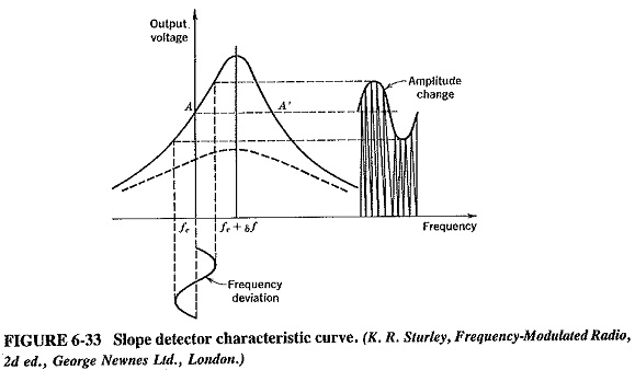
This output voltage is applied to a diode detector with an RC load of suitable time constant. The circuit is, in fact, identical to that of an AM detector, except that the secondary winding of the IF transformer is off-tuned. (In a desperate emergency, possible, after a fashion, to receive FM with an AM receiver, with the simple expedient of giving the slug of the coil to which the detector is connected two turns clockwise. Remember to reverse the procedure after the emergency is over!)
The Slope Detector FM Demodulation does not really satisfy any of the conditions laid down in the introduction. It is inefficient, and it is linear only along a very limited frequency range. It quite obviously reacts to all amplitude changes. Moreover, it is relatively difficult to adjust, since the primary and secondary windings of the transformer must be tuned to slightly differing frequencies. Its only virtue is that it simplifies the explanation of the operation of the balanced Slope Detector FM Demodulation.
Balanced slope detector:
The balanced slope detector is also known as the Travis detector (after its inventor), the triple-tuned discriminator (for obvious reasons), and as the amplitude discriminator (erroneously). As shown in Figure 6-34, the circuit uses two slope detectors. They are connected back to back, to the opposite ends of a center-tapped transformer, and hence fed 180° out of phase. The top secondary circuit is tuned above the IF by an amount which, in FM receivers with a deviation of 75 kHz, is 100 kHz. The bottom circuit is similarly tuned below the IF by the same amount. Each tuned circuit is connected to a diode detector with an RC load. The output is taken from across the series combination of the two loads, so that it is the sum of the individual outputs.
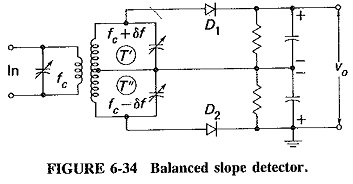
Let fc be the IF to which the primary circuit is tuned, and let fc + δf and fc – δf be the resonant frequencies of the upper secondary and lower secondary circuits T’ and T”, respectively. When the input frequency is instantaneously equal to fc, the voltage across T’, that is, the input to diode D1, will have a value somewhat less than the maximum available, since fc is somewhat below the resonant frequency of T’. A similar condition exists across T”. In fact, since fc is just as far from fc + δf as it is from fc – δf, the voltages applied to the two diodes will be identical. The dc output voltages will also be identical, and thus the detector output will be zero, since the output of D1 is positive and that of D2 is negative.
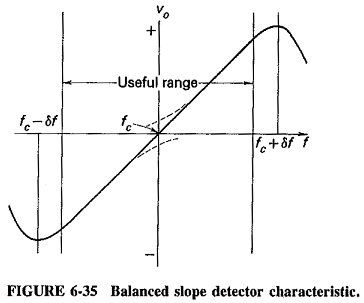
Now consider the instantaneous frequency to be equal to fc + δf. Since T’ is tuned to this frequency, the output of D1 will be quite large. On the other hand, the output of D2 will be very small, since the frequency fc + δf is quite a long way from fc – δf. Similarly, when the input frequency is instantaneously equal to fc – δf, the output of D2 will be a large negative voltage, and that of D1 a small positive voltage. Thus in the first case the overall output will be positive and maximum, and in the second it will be negative and maximum. When the instantaneous frequency is between these two extremes, the output will have some intermediate value. It will then be positive or negative, depending on which side of fc the input frequency happens to lie. Finally, if the input frequency goes outside the range described, the output will fall because of the behavior of the tuned circuit response. The required S-shaped frequency-modulation characteristic (as shown in Figure 6-35) is obtained.
Although this detector is considerably more efficient than the previous one, it is even trickier to align, because there are now three different frequencies to which the various tuned circuits of the transformer must be adjusted. Amplitude limiting is still not provided, and the linearity, although better than that of the single Slope Detector FM Demodulation, is still not good enough.