Level Detector:
Schmitt trigger or level detector circuits are very often employed in static relay circuits as a final stage before the trip coil circuit of the circuit breaker. The name level detector is derived from the fact that the circuit operates abruptly when the input level exceeds a predetermined value.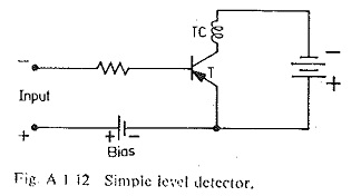
This is shown in Fig. A.1.12, which shows the principle of a level detector. Here there is normally a positive bias on the base of the transistor to keep it non-conducting as stated in the previous section. The transistor can be made to conduct or switch to operation, if the input voltage is made to exceed the input bias in the opposite direction i.e. the base is made negative with respect to its emitter.
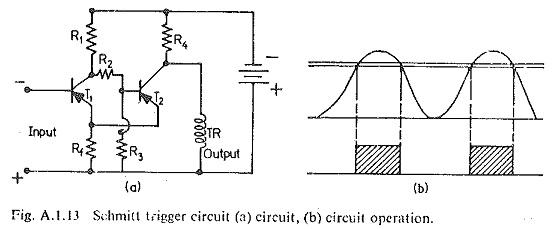
Fig, A.1.13(a) shows a more precise level detector with negative feedback applied to give snap action. Here the bias is obtained from the potentiometer R1,R2,R3 rather than a bias battery. In this circuit there are two transistors T1 and T2 (both p-n-p in this case). Here T1 is normally OFF and T2 is normally ON because of the negative feed-back resistor Rf and the bias applied to the base of T2 through the potentiometer R1,R2,R3. This circuit has high reset (drop out/pick up) ratio, while retaining the snap action. When the input voltage at the base of T1 exceeds the bias due to Rf the transistor T2 starts to conduct and the action becomes very rapid leading to the switching off of transistor T2. When this happens, an output voltage almost equal to the supply battery voltage is held at a voltage determined by the collector voltage of T1 and the potential divider R2,R3. This can facilitate the choice of the reset voltage as shown in Fig. A.I.13(b).