Types of Protective Relays:
Basically, Types of Protective Relays are analogue-binary signal converters with measuring functions. The variables such as current, voltage, phase angle or frequency and derived values obtained by differentiation, integration or other arithmetical operations, appear always as analogue signals at the input of the measuring unit. The output will always have a binary signal, i.e. either an open (or OFF) signal if the relay is not to trip or a close (or ON) signal if the relay is to trip. These output signals can therefore be easily evaluated by subsequent control elements requiring very little technical effort. Each types of protective relays is built up of individual elements in accordance with the basic block diagram shown in Fig. 1.1.
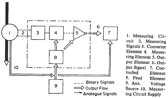
The signals, which occur in analogue and therefore in the continuously variable form from the measuring circuit (C.T and/or V.T) are first fed to the converter unit in the Types of Protective Relays. This converts the measured signals so that they can be easily processed by the measuring element which follows. This measuring element will be operated when the input signal reaches a certain value providing a close signal at its output. The controlled elements carry out the final switching functions as opening of circuit breakers, etc. Power is supplied to the measuring or output element by a feed element. This power is obtained either from an auxiliary voltage source or from the measuring circuit itself.
Converter Element:
This element contains chiefly the matching transformers to obtain the required signal level. The rest of the construction depends on whether one or two or more inputs are to be handled by the relay.
Relays for one quantity are supplied with only one electrical quantity, e.g. current or voltage. After suitable transformation by the matching transformers, this quantity is fed to diode bridges at whose output it appears as a d.c. variable with ripple. Through setting networks consisting of fixed and variable resistors, clipping diodes, etc. the measured value of the quantity is fed into a harmonic filter (if the speed requirements are not too stringent) since the subsequent measuring element deals only with d.c. variables. Sometimes smoothing filters are used to eliminate ripples, but in high speed relays such filters cannot be used.
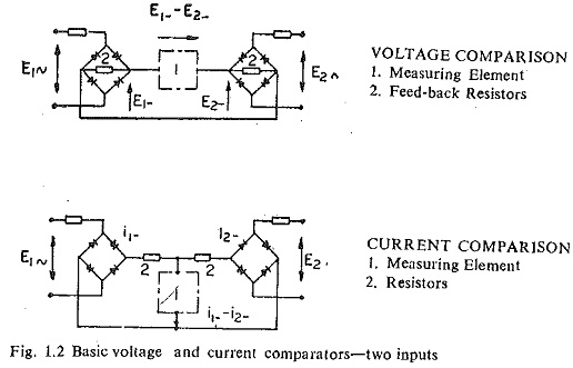
In relays for two quantities the converter element is fed at its input with two electrical quantities. In each case the comparison can be either amplitude or phase comparison between the two signals, the signals being converted to voltage or current signals (Fig. 1.2).
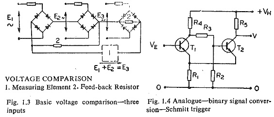
There is also a pulse type comparison in which one of the variables is converted into a pulse when passing through zero and the second is converted into a rectangular block.In relays for three or more quantities, the converter element is supplied with three or more electrical quantities. In Fig. 1.3 it will be noticed that in two of the measuring bridges the feed-back resistors are combined into one.
Measuring Element:
This is an analogue-binary signal converter with measuring functions. In the simplest form it consists of the Schmitt trigger circuit shown in Fig. 1.4 as the basic circuit. The Schmitt trigger circuit can be compared to an extremely fast polarized d.c. relay and acts as a level detector. Transistors are used in common emitter connection giving high input resistance and large current gain. The level detector gives a step output when the input voltages exceed a specified level.
Output Element:
This element amplifies the output signal from the measuring element, multiplies it, may combine it with certain other signals and also introduce a delay if necessary. Since it has to process only binary signals, this need net be a precision element. It may thus take the form of auxiliary relays or contactors. These provide potential separation between controlling and controlled circuits. It may also take the form of a bistable or monostable multivibrator circuit and if required modulated by logic circuits like AND, OR, NOR or timing elements. Where large powers are involved, e.g. operating trip coils of circut breakers, silicon controlled rectifiers (SCR) are used after the logic element.
Feed Element:
The function of this element is to supply the power necessary to operate the circuits and the power is obtained either from a built-in auxiliary or from station battery. In the feed element should supply a stabilized voltage to the static circuits, so that the measuring accuracy is not impaired. In the initial stages of developmet, nickel cadmium rechargeable cells. (commonly known as button cells) were used in the commercially produced static relays, specially in the U.K., but experience has shown that their reliability is poor. They are being given up at present and in their place station batteries with suitable taps at the appropriate voltages are being preferred. In the case of several types of relays, the supply is derived from the current and voltage transformers themselves, as Mentioned above with the refinement that the power supply to the relay is switched on only in case of a fault being detected by a suitable fault detector.