Directional Relays:
Selective protection cannot be achieved with time graded overcurrent protection systems in ring or loop systems as well as in radial circuits with two end power supply. A directional feature is incorporated in the Directional Relays as shown in Fig. (4.11).
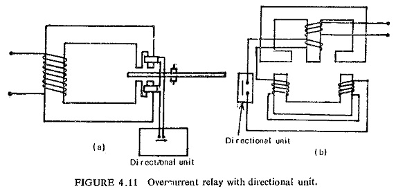
Figure (4.11a) shows how an induction disc type overcurrent relay with split-pole magnet, having in addition a directional unit consisting of capacitance or a resistance capacitance circuit works. Figure (4.11 b) shows the wattmetric type of induction disc relay. Here the directional unit controls the angle between the two fluxes by varying the RX parameters of the lower electromagnet.
Another method of control in the wattmetric element is to supply the lower winding from a separate voltage source. When the voltage of this source is equal and opposite to the output of the upper magnet secondary winding there is no current in the lower coil, and therefore no torque is produced. If it opposes and is less than the secondary output, or if it assists the secondary output, there is an operating torque.
Conversely, if this source voltage opposes and exceeds the secondary output the current in the lower coif is reversed, giving a reverse torque. This latter method of control is the basis of the Translay balanced-voltage unit protection.
Directional relays must have the following features:
- high speed of operation;
- high sensitivity;
- ability to operate with low values of voltage;
- adequate short-time thermal rating;
- burden must not be excessive; and
- there should be no voltage creep and current creep. That is, if either the voltage coil alone or the current coil alone is energized with the other one unenergized there should be no movement.
Induction cup units satisfy these requirements and are therefore very popular.