Directional High Frequency Antenna:
Directional High Frequency Antenna are likely to differ from lower-frequency ones for two reasons. These are the HF transmission/reception requirements and the ability to meet them. Since much of HF communication is likely to be point-to-point, the requirement is for fairly concentrated beams instead of omnidirectional radiation. Such radiation patterns are achievable at Directional High Frequency Antenna, because of the shorter wavelengths. Antennas can be constructed with overall dimensions of several wavelengths while retaining a manageable size.
Dipole Arrays:
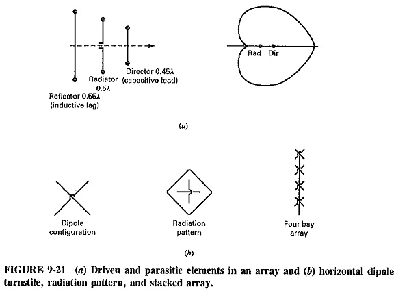
An antenna array is a radiation system consisting of grouped radiators, or elements (Figure 9-21). These are placed close together so as to be within each other’s induction field. They therefore interact with one another to produce a resulting radiation pattern that is the vector sum of the individual ones. Whether reinforcement or cancellation takes place in any given direction is determined not only by the individual characteristics of each element, but also by the spacing between elements, as measured in wavelengths, and the phase difference (if any) between the various feed points. By suitably arranging an array, it is possible to cause pattern cancellations and reinforcements of a nature that will result in the array’s having strongly Directional High Frequency Antenna characteristics. Gains well in excess of 50 are not uncommon, especially at the top end of the high-frequency band. It is also possible to use an array to obtain an omnidirectional radiation pattern in the horizontal plane, as with turnstile arrays (Figure 19-21b) used for television broadcasting. It is generally true to say that Directional High Frequency Antenna arrays are more likely to be used to obtain directional behavior rather than to create omnidirectional patterns.
Parasitic elements:
It is not necessary for all the elements of an array to be connected to the output of the transmitter, although this does, in fact, happen in quite a number of arrays. A radiating element so connected is called a driven element, whereas an element not connected is called a parasitic element. Such a parasitic element receives energy through the induction field created by a driven element, rather than by a direct connection to the transmission line. As a generalization, a parasitic element longer than the driven one and close to it reduces signal strength in its own direction and increases it in the opposite direction. It acts in a manner similar to a concave minor in optics and is called a reflector (Figure 9-21). A parasitic element shorter than the driven one from which it receives energy tends to increase radiation in its own direction and therefore behaves like the convergent convex lens, which is called a director. This is illustrated in Figure 9-21.
The large variety of types of arrays consist as a rule of dipoles arranged in specific physical patterns and excited in various ways, as the conditions require.
Broadside array:
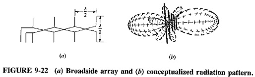
Possibly the simplest array consists of a number of dipoles of equal size, equally spaced along a straight line (i.e., collinear), with all dipoles fed in the same phase from the same source. Such an arrangement is called a broadside array and is shown in Figure 9-22, together with the resulting pattern.
The broadside array is strongly directional at right angles to the plane of the array, while radiating very little in the plane. The name comes from the naval term broadside. If some point is considered along the line perpendicular to the plane of the array, it is seen that this distant point is virtually equidistant from all the dipoles forming the array. The individual radiations, already quite strong in that direction, are reinforced. In the direction of the plane, however, there is little radiation, because the dipoles do not radiate in the direction in which they point, and because of cancellation in the direction of the line joining the center. This happens because any distant point along that line is no longer equidistant from all the dipoles, which will therefore cancel each other’s radiation in that direction (all the more so if their separation is λ/2, which it very often is).
Typical antenna lengths in the broadside array are from 2 to 10 wavelengths, typical spacing’s are λ/2 or λ, and dozens of elements may be used in the one array. Note that any array that is Directional High Frequency Antenna at right angles to the plane of the array is said to have broadside action.
End-fire array:
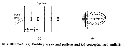
The physical arrangement of the end-fire array is almost the same as that of the broadside array. However, although the magnitude of the current in each element is still the same as in every other element, there is now a phase difference between these currents. This is progressive from left to right in Figure 9-23, as there is a phase lag between the succeeding elements equal in hertz to their spacing in wavelengths. The pattern of the end-fire array, as shown is quite different from that of the broadside array. It is in the plane of the array, not at right angles to it, and is unidirectional rather than bidirectional. Note that any array with that pattern arrangement is said to have end-fire action.
There is no radiation at right angles to the plane of the array because of cancellation. A point along the line perpendicular to the plane of the array is still equidistant from all the elements, but now the first and third dipoles are fed out of phase and therefore cancel each other’s radiation, as do the second and fourth dipoles, and so on. With the usual dipole spacing of λ/4 or 3λ/4, not only will there be cancellation at right angles to the plane of the array, as just described, but also in the direction from right to left in Figure 9-23. Not only is the first dipole closer by λ/4 to some distant point in that direction (so that its radiation is 90° ahead of that from the second dipole) but it also leads the second dipole by 90°, again by virtue of the feed method. The radiations from the first two dipoles will be 180° out of phase in this direction and will cancel, as will the radiations from the third and fourth dipoles, and so on. In the direction from left to right, the physical phase difference between the dipoles is made up by the phase difference in feeding. Therefore addition takes place, resulting in strong unidirectional radiation.
Both the end-fire and broadside arrays are called linear, and both are resonant since they consist of resonant elements. Similarly, as with any high Q resonant circuit, both arrays have a narrow bandwidth, which makes each of them particularly suitable for single-frequency transmission, but not so useful for reception where the requirement is generally the ability to receive over a wide frequency range.
Folded Dipole and Applications:
As shown in Figure 9-24, the folded dipole is a single antenna, but it consists of two elements. The first is fed directly while the second is coupled inductively at the ends. The radiation pattern of the folded dipole is the same as that of a straight dipole, but its input impedance is greater. This may be shown by noting (Figure 9-24) that if the total current fed in is I and the two arms have equal diameters, then the current in each arm is I/2. If this had been a straight dipole, the total would have flowed in the first (and only) arm. Now with the same power applied, only half the current flows in the first arm, and thus the input impedance is four times that of the straight dipole. Hence Rr = 4 X 72 = 288 Ω for a half-wave folded dipole with equal diameter arms.
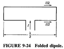
If elements of unequal diameters are used, transformation ratios from 1.5 to 25 are practicable, and if greater ratios are required, more arms can be used. Although the folded dipole has the same radiation pattern as the ordinary dipole, it has many advantages: its higher input impedance and its greater bandwidth, as well as ease and cost of construction and impedance matching.
The Yagi-Uda antenna:
A Yagi-Uda antenna is an array consisting of a driven element and one or more parasitic elements. They are arranged collinearly and close together, as shown in Figure 9-25, together with the optical equivalent and the radiation pattern.
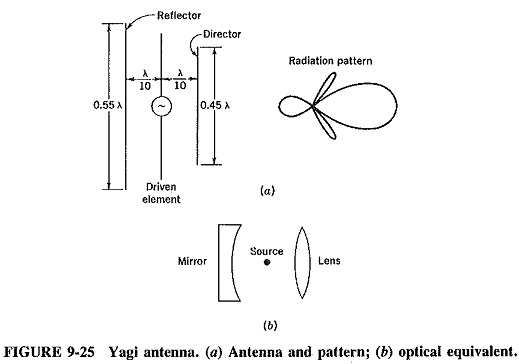
Since it is relatively unidirectional, as the radiation pattern shows, and has a moderate gain in the vicinity of 7 dB, the Yagi antenna is used as an Directional High Frequency Antenna. It is also employed at higher frequencies, particularly as a VHF television receiving antenna. The back lobe of Figure 9-25b may be reduced, and thus the front-to-back ratio of the antenna improved, by bringing the radiators closer. However, this has the adverse effect of lowering the input impedance of the array, so that the separation shown, 0.1λ, is an optimum value.
The precise effect of the parasitic element depends on its distance and tuning, i.e., on the magnitude and phase of the current induced in it. As already mentioned, a parasitic element resonant at a lower frequency than the driven element (i.e., longer) will act as a mild reflector, and a shorter parasitic will act as a mild “director” of radiation. As a parasitic element is brought closer to the driven element, it will load the driven element more and reduce its input impedance. This is perhaps the main reason for the almost invariable use of a folded dipole as the driven element of such an array.
The Yagi antenna admittedly does not have high gain, but it is very compact, relatively broadband because of the folded dipole used and has quite a good unidirectional radiation pattern. As used in practice, it has one reflector and several directors which are either of equal length or decreasing slightly away from the driven element. Finally, it must be mentioned that the folded dipole, along with one or two other antennas, is sometimes called a supergain antenna, because of its good gain and beamwidth per unit area of array.
Nonresonant Antennas—The Rhombic:
A major requirement for Directional High Frequency Antenna is the need for a multi-band antenna capable of operating satisfactorily over most or all of the 3- to 30-MHz range, for either reception or transmission. One of the obvious solutions is to employ an array of nonresonant antennas, whose characteristics will not change too drastically over this frequency range.
A very interesting and widely used antenna array, especially for point-to-point communications, is shown in Figure 9-26. This is the rhombic antenna, which consists of nonresonant elements arranged differently from any previous arrays. It is a planar rhombus which may be thought of as a piece of parallel-wire transmission line bowed in the middle. The lengths of the (equal) radiators vary from 2 to 8 λ, and the radiation angle, Φ, varies from 40 to 75°, being mostly determined by the leg length.
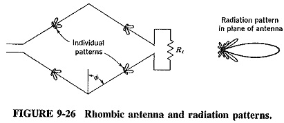
The four legs are considered as nonresonant antennas. This is achieved by treating the two sets as a transmission line correctly terminated in its characteristic impedance at the far end; thus only forward waves are present. Since the termination absorbs some power, the rhombic antenna must be terminated by a resistor which, for transmission, is capable of absorbing about one-third of the power fed to the antenna. The terminating resistance is often in the vicinity of 800 Ω and the input impedance varies from 650 to 700 Ω The directivity of the rhombic varies from about 20 to 90°, increasing with leg length up to about 8 λ. However, the power absorbed by the termination must be taken into account, so that the power gain of this antenna ranges from about 15 to 60°. The radiation pattern is unidirectional as shown (Figure 9-26).
Because the rhombic is nonresonant, it does not have to be an integral number of half-wavelengths long. It is thus a broadband antenna, with a frequency range at least 4 : 1 for both input impedance and radiation pattern. The rhombic is ideally suited to Directional High Frequency Antenna transmission and reception and is a very popular antenna in commercial point-to-point communications.