What is Vacuum Diode, Construction, Working and Applications:
Construction of Vacuum Diode – Vacuum diode is the simplest form of the electron tube for the production and control of free electrons. A typical vacuum diode is shown in Fig. 5.1. It consists of two electrodes—a cathode and an anode (or plate) mounted on a base and enclosed within a highly evacuated envelope of glass or metal. Cathode serves as an emitter of electrons and anode (or plate) surrounds the cathode and acts as a collector of electrons. The cathode may be a simple filament of tungsten or thoriated tungsten. Alternatively, it may be a nickel tube coated with barium oxide or strontium oxide and heated by an insulated filament, as illustrated in Fig. 5.1(c).
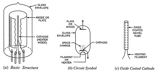
The greatest emission efficiencies are available with oxide-coated cathodes, but filament cathodes are toughest. Anode is usually a hollow metallic cylinder. In low-power tubes the anode is usually of nickel or iron but in case of high-power tubes, tantalum, molybdenum, or graphite may be employed because they do not deteriorate as rapidly as iron or nickel at high temperatures. The anode is made large enough to dissipate heat without excessive rise in temperature. Often the anode is fitted with cooling fins so as to remove the heat produced at the anode. Further the anode surface is usually blackened and roughened for easy removal of heat. The necessary pin connections are brought out at the bottom of the tube through airtight seals. The basic structure and circuit symbol of a vacuum diode are given in Figs. 5.1 (a) and (b) respectively.
Working of Vacuum Diode:
The operation of a diode is based on the basic law of electricity which states that like charges repel each other and unlike charges attract each other. Electrons emitted from the cathode of an electron tube are negative electric charges. These charges may be either attracted to or repelled from the anode of a diode tube, depending on whether the anode is positively or negatively charged.
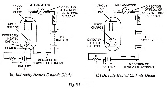
When a metallic cathode is heated sufficiently (directly or indirectly) an invisible cloud of electrons is set free in the space to form the space charge. The space charge exerts a repelling force on the electrons being emitted from the cathode. If the anode (or plate) is made positive w.r.t. cathode (by connecting anode to the positive terminal of an ht battery and cathode to the negative terminal, as illustrated in Fig. 5.2), an electric field is created extending from anode to cathode and the electrons from the space charge are attracted by the anode and consequently a current flows through the tube.
Upon reaching the plate the electrons continue to flow through the external circuit made up of connecting wire, milliammeter and the battery. The arriving electrons are absorbed into the +ve terminal of the battery and equal number of electrons flow out from -ve terminal of battery and return to the cathode, thus replenishing the supply of electrons lost by emission. As long as cathode of the tube is maintained at emitting temperature and the anode remains positive, electrons will continue to flow from cathode to anode within the tube and from anode back to cathode through external circuit. It should be noted that the direction of flow of electrons is opposite to the assumed or conventional direction of flow of current in the circuit. In case the anode is made negative with respect to cathode; electrons would be driven back to the cathode and no current would flow in the circuit. This is because neither the plate is made of suitable material for electron emission nor it is hot enough to emit electrons.
The operation of a vacuum diode may be concluded as follows:
- The diode conducts only when the anode or plate is made positive w.r.t. cathode. It will not conduct in opposite direction i.e. when anode is negative w.r.t. cathode.
- Electron flow within a diode takes place only from cathode to anode and never from anode to cathode. This unidirectional conduction enables the diode to act like a switch or valve, automatically starting or stopping conduction depending upon whether the plate is +ve or -ve with respect to cathode. This property permits the diode to act as a rectifier.
Characteristics of Vacuum Diode:
The magnitude of current that flows through a tube, known as anode or plate current, depends on both the number of electrons emitted by the cathode and the ability of the anode (or plate) to attract the electrons. The number of electrons emitted from the cathode depends on its temperature, which in turn depends on the strength of current flowing through the cathode or its heater. The ability of plate to attract the emitted electrons depends on the voltage between anode and cathode known as plate voltage. Thus the plate current of a diode depends on two factors (i) plate voltage and (ii) cathode temperature.
The circuit diagram for determining the characteristics of a diode is shown in Fig. 5.3.
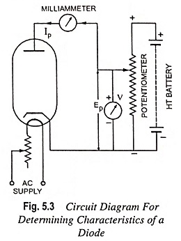
The most important characteristic of a vacuum diode is the plate characteristic which provides the relation between plate voltage, Ep and plate current, Ip. It can be determined by keeping the cathode temperature constant, varying the plate voltage with the help of movable tap over the potentiometer as shown, noting the corresponding values of plate current and plotting the curves between plate voltage and plate current. Different curves are obtained with different values of cathode temperature, as shown in Fig. 5.4.
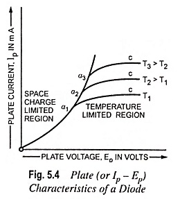
From the plate current-plate voltage characteristics shown in Fig. 5.4, it is seen that plate current Ip increases up to point `a’ with the increase in plate voltage, attains its maximum value at ‘a’ and if the plate voltage is further increased the plate current becomes almost constant as represented by flat curve ac. The reason of it is that when the plate voltage is low, all electrons emitted by cathode are not attracted by anode and they remain in the space between the cathode and anode and as the plate voltage is increased more and more electrons are attracted by the plate and consequently plate current increases with the increase in plate voltage. At point ‘a’ on the curve i.e. when the plate current attains its maximum all the electrons emitted by cathode are attracted by anode and further increase in plate voltage will not cause any appreciable increase in plate current so that the Ip – Ep characteristic curve of a diode becomes approximately a horizontal line, as shown in the figure. If the cathode temperature is increased from T1 to T2 or to T3 absolute by increasing the heater current the plate current will further increase as shown by the curves drawn for temperatures T2 and T3 respectively. Thus at low values of plate voltage the plate current is limited by space charge and varies according to Child’s three halves power i.e. Ip = k Ep3/2 where k is a constant depending upon the shape of the electrodes and geometry of the tube.
Thus we see that there are two major regions of the plate characteristics of a diode—the space charge limited region, and the temperature-limited region. The diode is operated in its space-charge limited region when more electrons are being produced at the cathode than are being drawn to the plate.
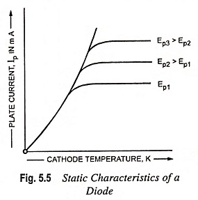
The static characteristics of a vacuum diode providing relation between plate current and cathode temperature can be determined by using the circuit shown in Fig. 5.3. Curves are drawn between plate current and cathode temperature keeping plate voltage constant. Two or three similar curves are obtained for different values of plate voltage, as shown in Fig. 5.5. From the plate current—cathode temperature characteristics it is obvious that the plate current increases rapidly with the increase in cathode temperature. For a particular value of plate voltage a temperature is reached when the plate current does no longer increase with temperature but becomes constant due to space charge saturation. If plate voltage is increased, the space charge saturation will occur at some higher point.
Diode Plate Resistance:
From plate characteristics of a vacuum diode (Fig. 5.4) we see that plate current, Ip varies with the variations in plate voltage, Ep. So, a diode may be considered to have an internal resistance limiting the magnitude of plate current. This internal resistance offered by the diode is known as its plate resistance. The plate resistance of a diode is mainly due to negative space charge and to a lesser extent depends upon the physical size and spacing of the electrodes. This resistance is not the same for dc and ac and so like any other vacuum tube, diode has two types of resistances, viz. dc plate resistance and ac plate resistance.
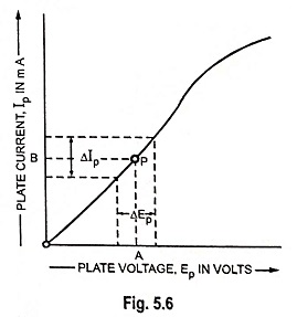
The resistance offered by a diode to direct current is called the dc plate resistance, Rp. It can be determined by determining the ratio of total dc plate voltage across diode to the plate current. At any point P on the plate characteristic curve (Fig. 5.6), the plate voltage is OA and the corresponding plate current is OB.
Then by Ohm’s law, dc plate resistance,
DC plate resistance is not constant but depends on the operating point on plate characteristic of the diode. It is different at different points, as illustrated in Fig. 5.6. This is because the plate characteristic of the diode is not a straight line.
The resistance offered by a diode to alternating current is known as ac plate resistance, rp. It is defined as the ratio of a small change in plate voltage across a diode to the resulting change in plate current i.e.,
AC plate resistance,
For the operating point P on the plate characteristic, the inverse of the slope of the tangent line to the characteristic at point P provides ac plate resistance.
As the tubes are generally operated with ac, therefore, ac plate resistance is much more important than dc plate resistance. The ac plate resistance can be determined from plate characteristic by considering a small change of plate voltage half way on each side of the operating point. The ac plate resistance of a diode is also called its dynamic resistance.