What is Metadyne Control? – Construction, Working and Applications:
The metadyne control system is based on constant current system of speed control. In resistance control or series- parallel control a great deal of energy is dissipated in the starting resistance and jerks are experienced when the controller of the starter moves from one position to another position. In metadyne control, current throughout the accelerating period remains constant, therefore, uniform tractive effort is developed and very smooth control, without causing any wastage of energy in the starting resistance, is achieved.
Construction of Metadyne:
The essential part of the metadyne control is metadyne converter. The metadyne converter is a cross-field machine which behaves like a transformer on direct current. The transformation ratio of a metadyne can he varied continuously. It takes power at constant voltage and variable current and delivers the same at constant current and varying voltage.
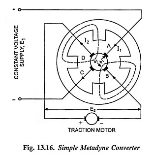
The metadyne converter essentially consists, in its simplest form, of a 2 pole dc armature with two pairs of brushes and a four pole field magnet, as shown in Fig. 13.16. One pair of the brushes (say A and C) are connected across constant voltage dc supply while the other pair (B and D) are connected to the load (normally a dc series motor).
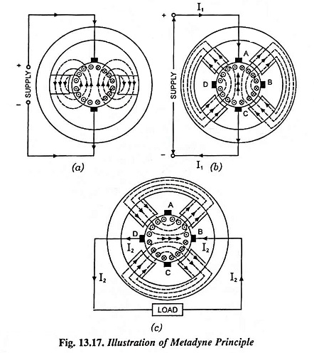
For understanding the working of a metadyne converter consider first an ordinary dc machine with two poles and two brushes supplied with a current flowing in the direction shown in Fig. 13.17 (a). It will cause armature current distribution, as illustrated in the figure with corresponding cross flux, mainly confined to the poles.
Working Principle of Metadyne:
Now consider that metadyne converter (a dc machine with two pairs of brushes and two pairs of poles) is running at constant speed and drawing a current I1 from the dc supply main, which flows through the armature conductors via the brushes A and C, as shown in Fig. 13.17 (b). An armature reaction flux Φ1 set up in usual way is provided with a fairly low reluctance path through the yoke by the four poles, as shown in the figure. Due to rotation of armature conductors in this primary flux, and emf E2 = KI1 is set up between the brushes B and D. When these brushes B and D are connected to a load, a current I2 flows through the load. The load current I2 sets up another flux Φ2 known as secondary flux, at the right angles to the first, the distribution is shown in Fig. 13.17 (c). This secondary flux Φ2 causes an emf, E1 = KI2 between brushes A and C opposing the applied voltage. As the applied voltage is constant, the resistance drop is negligible so the back emf E1 opposing applied voltage and the current I2 producing E1 are also constant.
Since input = E1I1 = KI2I1 = KI2 x E2/K = E2I2 = output, therefore, power required to drive the metadyne is very small being equal to the running losses of the machine.
This simple metadyne converter transforms the constant voltage supply into a constant current variable voltage supply to feed the load. The arrangement, therefore, is quite suitable for starting dc traction motors. With this arrangement the load current I2 and supply voltage V remain constant and as the load increases on account of building of back emf in dc traction motor E2 and I1 increases to meet with the increased load.
The metadyne described above has no winding on the poles and is capable of delivering only a single value of constant current but for supplying dc traction motors, after the motor has gained speed, the load current I2 has to be reduced to the running value. For this purpose the field magnet poles are provided with variator and regulator windings, as shown in Fig. 13.18.
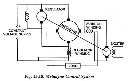
The variator winding sets up a flux in the same direction as that set up by the load current I2. Total flux Φ2 required in this axis being constant in order to produce a back emf E1 equal to the constant supply voltage, therefore if some of this flux is set up by a separate winding, known as variator winding, the load current I2 will decrease and can be of a smaller constant value. Similarly the load current can be increased by causing the current to flow in the variator winding in the opposite direction.
If the output current I2 is, say, reduced in this way, the voltage remaining the constant, the total output will be reduced but input will remain the same and therefore, the set will speed up. In order to keep the speed of the metadyne converter constant, an additional winding known as regulator winding is provided. By adjusting the current in the regulator winding, the input current can be varied and therefore, input power can be adjusted equal to output power, the speed of the converter remaining the same.
The regulator winding is supplied from a small dc shunt generator mounted on the shaft of the metadyne. Any tendency towards a change in speed of the metadyne will cause corresponding change in the emf set up by the shunt machine and as it acts in the opposite direction of the supply voltage, so corresponding change in the regulator winding current will result in.
The variator winding is supplied excitation from an exciter mounted on the same shaft, as shown in Fig. 13.18.
With metadyne converter, regenerative braking can be accomplished very easily by reversing the field of the traction motor. This causes the reversal of direction of induced emf E2 which in turn will change the direction of current I1. Thus current I1 can be supplied back to the supply source. By controlling the magnitude of reversed excitation of traction motors supplied by metadyne, the magnitude of regenerative braking can be regulated.
Application of Metadyne Control:
The metadyne is employed whenever control of dc motors is required. The control provided by the metadyne is smooth and does not require any switching. Thus switchgear and arcing are avoided. In some cases it is cheaper than the Ward Leonard system in initial cost. In traction it provides smooth acceleration without skill on the part of driver and regenerative braking down to very slow speeds. The savings due to these items may easily counterbalance the additional cost of the more complicated equipment required and its additional maintenance cost. It is already being employed in the underground railway.