What is DIAC? – Symbol, Construction, Operation and Applications
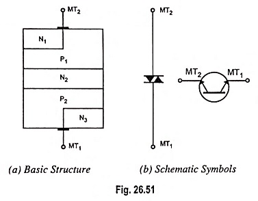
A diac is an important member of the thyristor family and is usually employed for triggering triacs. A diac is a two electrode bidirectional avalanche diode which can be switched from off-state to the on-state for either polarity of the applied voltage. This is just like a triac without gate terminal, as shown in Fig. 26.51 (a). Its equivalent circuit is a pair of inverted four layer diodes. Two schematic symbols are shown in Fig. 26.51 (b). Again the terminal designations are arbitrary since the diac, like triac, is also a bilateral device. The switching from off-state to on-state is achieved by simply exceeding the avalanche breakdown voltage in either direction.
Construction of DIAC:
A diac is a P-N-P-N structured four layer, two terminal semiconductor device, as shown in Fig. 26.51 (a). MT2 and MT1 are the two main terminals of the device. There is no control terminal in this device. From the diagram, a diac unlike a diode, resembles a bipolar junction transistor (BJT) but with the following exceptions.
- there is no terminal attached to the middle layer (base),
- the three regions are nearly identical in size,
- the doping level at the two end P-layers is the same so that the device gives symmetrical switching characteristics for either polarity of the applied voltage.
DIAC Working Principle:
When the terminal MT2 is positive, the current flow path is P1-N2-P2-N3 while for positive polarity of terminal MT1 the current flow path is P2-N2-P1-N1. The operation of the diac can be explained by imagining it as two diodes connected in series. When applied voltage in either polarity is small (less than breakover voltage) a very small amount of current, called the leakage current, flows through the device. Leakage current caused due to the drift of electrons and holes in the depletion region, is not sufficient to cause conduction in the device. The device remains in nonconducting mode. However, when the magnitude of the applied voltage exceeds the avalanche breakdown voltage, breakdown takes place and the diac current rises sharply, as shown in the characteristics shown in Fig. 26.52.
VI Characteristics of DIAC:
Volt-ampere characteristic of a diac is shown in Fig. 26.52. It resembles the English letter Z because of the symmetrical switching characteristics for either polarity of the applied voltage.
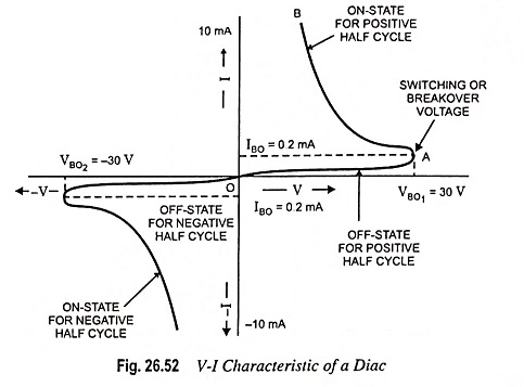
The diac acts like an open circuit until its switching or breakover voltage is exceeded. At that point the diac conducts until its current reduces toward zero (below the level of the holding current of the device). The diac, because of its peculiar construction, does not switch sharply into a low voltage condition at a low current level like the SCR or triac. Instead, once it goes into conduction, the diac maintains an almost continuous negative resistance characteristic i.e., voltage decreases with the increase in current. This means that, unlike the SCR and the triac, the diac cannot be expected to maintain a low (on) voltage drop until its current falls below a holding current level.
DIAC Application:
The diacs, because of their symmetrical bidirectional switching characteristics, are widely used as triggering devices in triac phase control circuits employed for lamp dimmer, heat control, universal motor speed control etc.
Although a triac may be fired into the conducting state by a simple resistive triggering circuit, but triggering devices are typically placed in series with the gates of SCRs and triacs as they give reliable and fast triggering. Diac is the most popular triggering device for the triac. This is illustrated in the following applications.
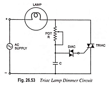
1. Triac Lamp Dimmer Circuit: The circuit for a triac controlled by an R-C phase-shift network and a diac is given in Fig. 26.53. This circuit is an example of a simple lamp dimmer. The triac conduction angle is adjusted by adjusting the potentiometer R. The longer the triac conducts, the brighter the lamp will be. The diac acts like an open circuit until the voltage across the capacitor exceeds its breakover or switching voltage (and the triac’s required gate trigger voltage).
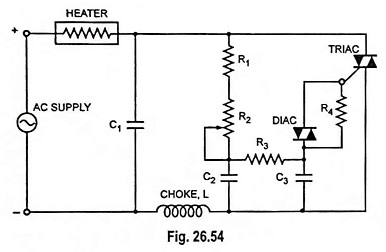
2. Heat Control Circuit: A typical diac-triac circuit used for smooth control of ac power to an heater is shown in Fig. 26.54. The capacitor C1 in series with choke L across the triac helps to slow up the voltage rise across the device during off state. The resistor R4 across the diac ensures smooth control at all positions of potentiometer R2. The triac conduction angle is adjusted by adjusting the potentiometer R2. The longer the triac conducts, the larger the output will be from the heater. Thus a smooth control of the heat output from the heater is obtained.