Balanced Slope Detector – Working, Advantages and Disadvantages:
The circuit of a balanced slope detector is shown in Fig. 22.53 (a). This circuit employees two slope detectors connected back to back to the opposite ends of a centre tapped secondary of the transformer. Thus voltages supplied to the two sides are in phase opposition.
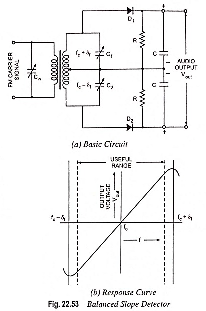
The upper secondary parallel resonant circuit is tuned to frequency fc + δf, where fc is the centre carrier frequency and δf is the deviation in FM receivers (75 kHz to 100 kHz). The lower secondary parallel circuit is tuned to frequency fc – δf. Each circuit is connected to a diode detector with an R-C load. The output is connected across the series combination of the two R-C loads. Thus the total output is equal to the sum of the individual outputs.
The parallel resonant circuit on the primary side is tuned to centre carrier frequency fc. When the input frequency is instantaneously equal to fc, the voltage across half has a value somewhat less than the maximum possible as fc is somewhat less than the resonant frequency of the upper secondary parallel resonant circuit. This voltage is supplied to diode D1. A similar condition exists across lower secondary parallel resonant circuit. But as the resonant frequencies (fc + δf) and (fc – δf) of upper and lower resonant circuits are symmetrically disposed w.r.t. centre carrier frequency fc, the voltage supplied to diodes D1 and D2 are equal. The dc output voltages will also be equal and the detector output voltage will be equal as the two dc output voltages oppose each other.
Now consider the instant when the instantaneous frequency is (fc + δf). Now the upper parallel resonant circuit is tuned to this incoming frequency and the output of diode D1 is quite large. On the other hand the output of diode D2 is very small because the incoming frequency (fc + δf) is far away from the resonance frequency (fc – δf) of the lower resonant circuit. Similarly when the input frequency is instantaneously equal to (fc – δf) the output of diode D2 is quite large negative voltage and that of diode D1 is quite small positive voltage. Thus, in the former case, the total output voltage Vout will be positive and maximum while in the latter case it will be negative and maximum. For the values of frequency in between these two extremes, the output voltage Vout will have some intermediate value, positive or negative depending on whether the instantaneous value is higher or lower than centre carrier frequency fc. Finally if the frequency lies outside the range described above, the output voltage will decrease because of the behavior of the tuned circuit response. The response curve (the relation between the output voltage Vout and instantaneous frequency f) of the balanced slope detector is shown in Fig. 22.53 (b).
Advantages and Disadvantages:
This FM detector is considerably more efficient than only slope detector and gives more linear response over the useful frequency range. However, it is difficult to align as it involves three resonant circuits tuned to three different frequencies. Further amplitude limiting is not provided.