Linear Diode Detector or Envelope Detector:
Diode detection is called the envelope detection as it recovers the audio frequency signal envelope from the composite signal. Diode detector is also called the linear detector as its output is proportional to the voltage of the input signal.
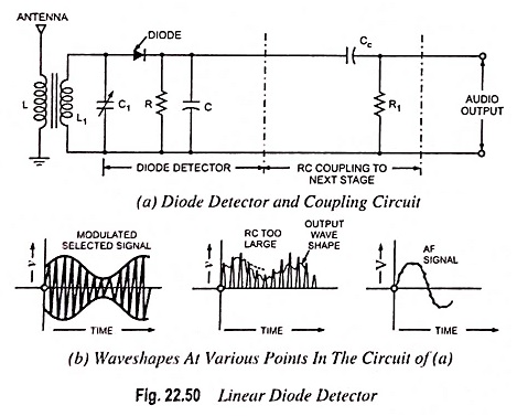
Linear diode detector makes use of rectification property of a diode. Such detectors are widely used in commercial radio receivers. However, a linear diode detector needs a carrier voltage of 5 V or more so as to provide satisfactory operation. With such a high value carrier voltage the cutin voltage of the diode may be neglected and the operation may be considered to be taking place over the linear portion of the dynamic voltage-current characteristic of the diode. The circuit of a basic diode detector is shown in Fig. 22.50. Here L1-C1 is a parallel resonant circuit. By varying C1, the resonant frequency of this circuit can be varied and hence RF signal of any frequency can be tuned in. It is to be noted that the antenna receives various modulated signals of different frequencies from various stations and the desired frequency is to be tuned in. The modulated selected signal is now applied to the junction diode. The diode conducts when the carrier signal is positive and cuts off when it is negative. Consequently, each positive half cycle of the carrier wave appears across the parallel combination of R and C in the manner depicted in Fig. 22.50(b). The capacitor C charges to nearly the peak value of the positive half cycle of the carrier wave. A small voltage drop occurs across the diode.
During the negative half cycle of the carrier the capacitor C discharges through the resistor R at a time constant RC. In choosing R and C care must be taken not to select too small a value for RC, otherwise the charge will be dissipated and the voltage will be reduced to zero during the negative half cycle. This condition can be avoided by choosing RC large compared to time it takes for the carrier to pass through one cycle. On the other hand, it is important that RC not be chosen excessively large, for then the capacitor will discharge so slowly that in the decreasing portion of the rectified output diagonal clipping occurs as indicated in Fig. 22.50(b). The best value of RC is that which causes the rate of discharge of the capacitor to follow the variations in the modulating signal. Analysis shows that the maximum permissible value of time constant RC for avoiding negative peak clipping is given by
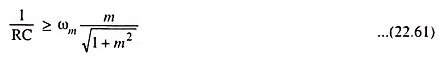
The analysis, however, neglects many factors which affect the results appreciably. So the maximum permissible value based on empirical formula is given as
![]()
The output signal of the diode detector has somewhat jagged variation depicted in Fig. 22.50(b). It has a waveshape that very closely resembles to that of the modulating signal, with the exception that it contains a dc level. This, however, is readily removed by using capacitance-resistance coupling to the next stage, as shown in Fig. 22.50(a). The output of this coupling network is a signal that very closely matches the original modulating signal.
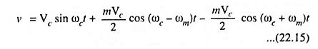
Mathematical Analysis: From Eq. (22.15)
![]()
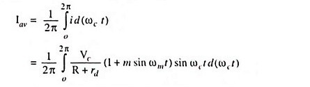
The current during conduction period is

where rd is the diode resistance for 0 ≤ ωc t ≤ π
So
sin ωm t term is assumed to be constant because ωm << ωc
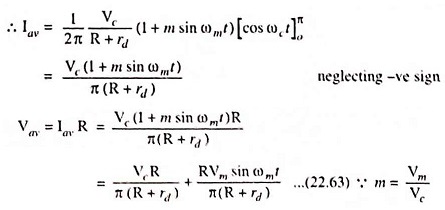
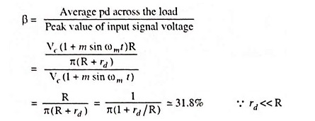
In above Eq. (22.63) the first term represents a dc component and the second term represents the ac component, the value of which is proportional to the modulating voltage. By processing the second term, information can be extracted.
Detection efficiency,
Advantages of Diode Detectors:
- They can be operated as linear or power detectors.
- They can handle comparatively large input signals.
- Good linearity is achieved, as negligible distortion is introduced during rectification.
- They can be used in simple automatic gain control circuits.
Disadvantages:
- During conducting period the diode consumes some power, so Q of its timed circuit along with its gain and selectivity is reduced.
- The diode detectors are not capable of amplifying the rectified signal by themselves as is possible in case of transistor detector. However, signal can be amplified both before and after rectification so this drawback does not matter much.