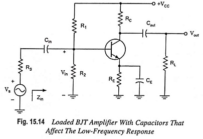
Low Frequency Response of BJT Amplifier:
For analysis, we will consider the loaded voltage-divider BJT bias configuration. But the results can be applied to any configuration. For the network shown in Fig. 15.14 the capacitors Cin, Cout and CE will determine the low frequency response of BJT Amplifier.
Now we will examine the impact of each independently.
Effect of Cin on Frequency Response of Amplifier:
Since Cin is normally connected between the applied source and the active device, the general form of the R-C combination is established by the network shown in Fig. 15.15.
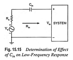
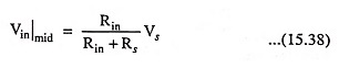
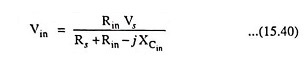
The total resistance is now (Rs + Rin) and the cutoff frequency is
![]()
At mid or high frequencies, the reactance of the capacitor Cin will be considerably small to allow a short-circuit approximation for the element. The relation between Vin and Vs is given as
At fLi, input voltage Vin will be 0.707 times the value determined by above Eq. (15.38), assuming that Cin is the only capacitive element that controls the Low Frequency Response of BJT Amplifier.
For the network given in Fig. 15.14, in analysis of the effects of Cin, we must assume that the capacitors CE and Cout are performing their de-signed function or the analysis becomes too unwieldy, that is, that the magnitudes of the reactances of Cout and CE allow using a short-circuit equivalent as compared to the magnitude of the other series impedances. Using this hypothesis, the ac equivalent network for the input section of the circuit shown in Fig. 15.14 will become as shown in Fig. 15.16.
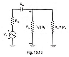
The value of Rin is given by the equation
![]()
The voltage Vin applied to the input of device can be determined by using voltage-divider rule and is given as
Thus with the decrease in frequency, the reactance of the capacitor Cin increases, some of the signal or source voltage is lost across the input capacitor Cin and the voltage Vin applied to the input of the device is reduced resulting in decrease in output voltage and hence the gain.
Effect of Cout on Frequency Response of Amplifier:
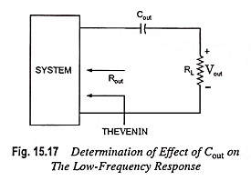
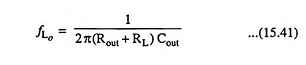
Since the output capacitor is normally connected between the output of the active device and the load, the R-C configuration determining the lower cutoff frequency due to Cout will appear as given in Fig. 15.17. From Fig. 15.17, the total series resistance is now Rout + RL and the cutoff frequency due to Cout is given by equation
Ignoring the effects of Cin and CE, the output voltage will be 70.7% of its midband value at fLo. For the network shown in Fig. 15.14, the ac equivalent network for the output section with Vin = 0, will appear as shown in Fig. 15.18.
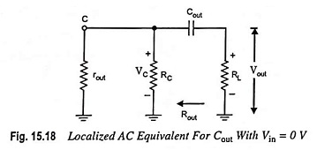
The value of Rout is given by the equation
![]()
Effect of CE on Frequency Response of Amplifier:
For determination of frequency fLe, the network “seen” by CE must be determined as illustrated in Fig. 15.19.
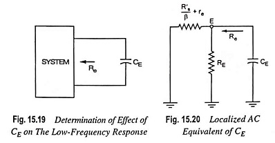
Once the level of Re is determined, the cutoff frequency due to CE can be computed from the relation
![]()
For the network shown in Fig. 15.14, the ac equivalent as ‘seen’ by CE will be as given in Fig. 15.20.
The value of Re is given by the equation
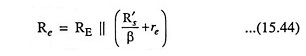
where R′s = Rs || R1 || R2
The effect of CE on the gain is best described in a quantitative manner by recalling that the gain for the configuration shown in Fig. 15.21 is given as
![]()
The maximum gain will obviously be for RE = 0 Ω. At low frequencies, with the bypass capacitor CE is its “open-circuit” equivalent state, all of RE appears in the above voltage gain equation, resulting in minimum gain.
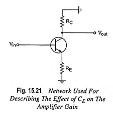
With the increase in frequency, the reactance of capacitor CE decreases, reducing the parallel impedance of RE and CE until the resistor RE is effectively “shorted out” by CE. The result is a maximum or midband gain given by equation Av = -RC/re. At fLE the gain will be 3 dB down the midband value determined with RE “shorted out.”