Controller Design Frequency Response:
The Controller Design Frequency Response (or root locus) alters or reshapes the frequency response (or root locus) of the original system to the desired one. Thus the ideal goal of compensation is to achieve a control system which has a desired performance, viz. having zero steady- state error, optimised dynamic performance, (which is neither too fast nor too slow) assuring the stability of the system, which is a necessary condition of a control system. The transient response must be damped out satisfactorily.
Basically employing a controller improves the behaviour by
- compensating or modifying one or more large time constants
- limiting the upper frequency so that a number of small time constants may lose their significance as well as their effect on the control system.
A system is in general considered to be optimum as far as its dynamic behaviour is concerned if it transmits all the operating frequencies in a similar way. This can be satisfied if the system has a transfer function
![]()
whose magnitude is constant for all frequencies, or at least for a large range of frequencies. Further, for the transfer function to satisfy this condition it must have all possible derivatives with respect to ω zero.
![]()
Using this criterion on the transfer function indicated in Eq. 6.70, the constants ao, a1, a2,…..,bo, b1, b2,… etc. can be evaluated. The Controller Design Frequency Response transfer function obtained this way gives optimum behaviour and the principle is called magnitude optimum. This procedure optimises a system so that it can pass a range of frequencies.
The resulting transfer function can be represented by Bode plots, or the time response can be determined if possible, to check whether the modified system gives the required performance.
Bode plots can also be employed to Controller Design Frequency Response to impart the desired performance to the system. The design criteria in this case can be taken as phase margin, φ = 180 — co,. This assures that the phase angle at the gain cross-over has a prescribed minimum value.
A close examination of the methods confirms that the designs are not very much different. They are effective in compensating large time constants.
The ratio of the integrating time constant of the controller and uncompensated time constant of the system decides this damping, and has a fixed value. Consequently the system has a fixed phase margin given by the damping. In the other method the designer has a latitude in choosing the ratio of time constants and hence has control over damping as well as phase margin. As it is always necessary for both the phase and gain margin of a system to be specified simultaneously, the Controller Design Frequency Response using phase margin criterion will also have a satisfactoty gain margin. Both the methods are also suitable if frequency response results are available in a graphical form from an experiment and cannot be represented by analytical expressions. The methods are discussed in detail in the following.
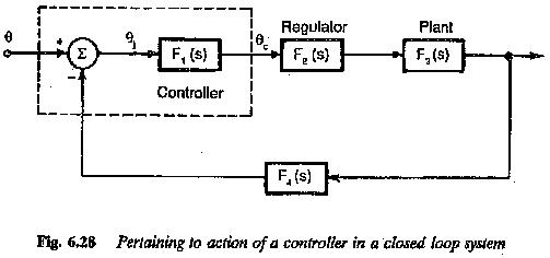
A Controller Design Frequency Response used can compensate maximum of two large time constants. The rise time is decided by the sum of all time constants which are not compensated and are significant in the working range of frequencies. However if the original control system has more than two large time constants the uncompensated time constants make the dynamic response slow and it may not be to the desired level. In such cases an inner subordinate loop can be employed to compensate for this time constant.
Generally in the control of drives besides the outer speed loop there is also an inner current loop, to have improved performance. Without introducing any appreciable error the controller transfer function of the inner loop can be approximated to a first order system.
The compensation described above, viz. compensating two large time constants, does not give satisfactory results if the system also has an integration. The design of controller based on the above criteria for use with such a system imparts an oscillatory behaviour. Hence the basis of the design of the controller must be changed in such a case. The Controller Design Frequency Response in this case also must be such that the magnitude of frequency response is unity for a wide range of frequencies, i.e., the system allows a wide range of frequencies to pass through. This gives an optimised controller and the method is called symmetrical optimum. The method is given the name because the frequency response is symmetrical with respect to gain cross-over frequency.