Methods of Compensation in Control System:
The Different Methods of Compensation in Control System are
- Cascade Compensation
- Feedback Compensation
- Load Circuit Compensation
- Input Circuit Compensation
A drive system having closed loop control may not be satisfactory with regard to its stability characteristics, speed of response and steady-state accuracy. The system may be oscillatory or even unstable. It may have either extremely fast or very sluggish response. The errors under steady-state between the actual and desired values may be excessive and not acceptable. Therefore, a necessity arises to modify the system or system parameters to provide the desired performance with respect to the above characteristics. This has certain practical limitations, such as size, range, and cost of available components. Sometimes there may not be any room to effect the change in the parameters.
In such cases the performance of the drive is improved by adding additional components to it. The method of improving the performance in this way is called compensation. The additional component changes the transfer function of the overall system and gives the desired performance. In feedback systems the compensation added is simple and less expensive and provides substantial improvement in the performance.
The design of a Methods of Compensation in Control System network to achieve the required improvement in the performance can be based on the frequency response plots or the root locus techniques. discussed.
The compensations introduced in the closed loop system to improve the performance reshapes the root locus or frequency response of the system. With this the system is stable, has satisfactory transient response, and has a steady-state error within the acceptable tolerance level, or even sometimes zero. The purpose of providing a Methods of Compensation in Control System, either by means of reshaping the frequency response or root locus may generally fall into one of the following categories:
- The system may be stable having the desired transient response but its steady state error is large.
- The given system may be stable, having a time response which is not
- The given system may be stable, but both the transient response and the steady-state error are not acceptable.
- The system may be unstable for all values of gain.
Ideal integral compensation increase the type of the system. An increase in the type of system completely eliminates the steady-state error. Therefore for a system having steady-state error with satisfactory transient response, a PI compensation is used (proportional and integral). Proportional control improves the stability. The improved system will have acceptable transient response.
PD compensation is used if the transient response has to be improved. It is equivalent to introducing an anticipation into the system. The derivative action increases the speed of response when the input is rapidly changing.
It has already been shown and brought out how
- the response of a second order system is altered by variation of damping
- the stability criteria such as Nyquist and Routh Hurwitz criteria can be used to study the effect of variation of parameters on the system stability
- how the root locus based on open loop transfer function can be used to study the variation of parameters to improve the performance of the system by investigating the sensitivity of the system for parameter
The design of controllers and compensators to improve the system performance will be discussed in the following. The design may be based on Bode plots or root locus techniques. The dynamics of the control system is altered or improved by the adjustments of the controller parameters and not the plant parameters. The adjustments change the controller transfer function.
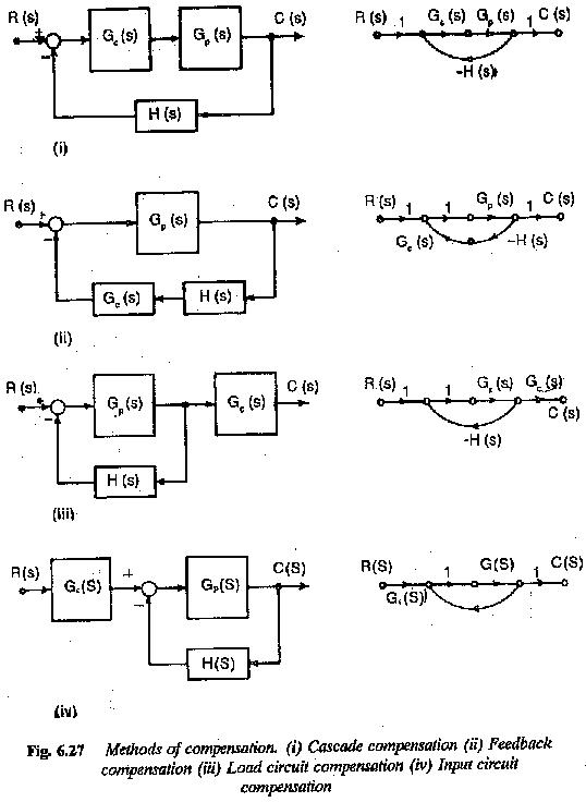
The controller providing compensation can be placed either in series with the plant in the forward path or in the feedback path. In the former it is called series (or cascade) compensation and in the latter parallel compensation. These are depicted in Fig. 6.27. The location of the compensation depends on the control system and the modifications required on the response.
A controller used in a feedback control system provides a corrective action depending upon the error between the actual and desired value of the quantity. The output of the control depends upon the state of the error. The controller component is identified in Fig. 628. The relationship between the output and the input of the controller is known as controller action θc(s) / θi(s) = f1(s) where θc(s) and θi(s) are the output and input of controller respectively.