What is Shunt Compensation in Power System?:
Shunt Compensation are connected in shunt at various system nodes (major substations) and sometimes at mid-point of lines. These serve the purposes of voltage control and load stabilization. As a result of installation of shunt compensation in the system, the nearby generators operate at near unity pf and voltage emergencies mostly do not arise. The two kinds of compensators in use are:
- Static var compensators (SVC): These are banks of capacitors (sometimes inductors also for use under light load conditions)
- STATCOM: static synchronous compensator
- Synchronous condenser: It is a synchronous motor running at no-load and having excitation adjustable over a wide range. It feeds positive VARs into the line under overexcited conditions and negative VARS when under excited.
It is to be pointed out here that SVC and STATCOM are static var generators which are thyristor controlled. In this section SVC will be detailed while STATCOM forms a part of FACTS.
Static VAR Compensator (SVC):
These comprise capacitor bank fixed or switched (controlled) or fixed capacitor bank and switched reactor bank in parallel. These compensators draw reactive (leading or lagging) power from the line thereby regulating voltage, improve stability (steady-state and dynamic), control overvoltage and reduce voltage flicker. These also reduce voltage and current unbalances. In HVDC application these compensators provide the required reactive power and damp out subharmonic oscillations.
Since static var compensators use switching for var control. These are also called static var switches or systems. It means that terminology wise
![]()
and we will use these interchangeably.
Basic SVC Configurations (or Designs):
Thyristors in antiparallel can be used to switch on a capacitor/reactor unit in stepwise control. When the circuitry is designed to adjust the firing angle, capacitor/reactor unit acts as continuously variable in the power circuit.
Capacitor or capacitor and inductor bank can be –varied stepwise or continuously by thyristor control. Several important SVS configurations have been devised and are applied in shunt line compensation. Some of the static compensators schemes are discussed in what follows.
(i) Saturated reactor:
This is a multi-core reactor with the phase windings so arranged as to cancel the principal harmonics. It is considered as a constant voltage reactive source. It is almost maintenance free but not very flexible with respect to operating characteristics.
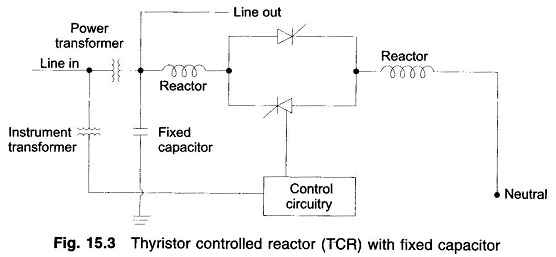
(ii) Thyristor-controlled reactor (TCR):
A thyristor-controlled-reactor (Fig. 15.3) compensator consists of a combination of six pulse or twelve pulse thyristor-controlled reactors with a fixed shunt capacitor bank. The reactive power is changed by adjusting the thyristor firing angle. TCRs are characterized by continuous control, no transients and generation of harmonics. The control system consists of voltage (and current) measuring devices, a controller for error-signal conditioning, a linearizing circuit and one or more synchronizing circuits.
(iii) Thyristor switched capacitor (TSC):
It consists of only a thyristor-switched capacitor bank which is split into a number of units of equal ratings to achieve a stepwise control (Fig. 15.4).
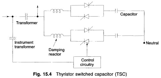
As such they are applied as a discretely variable reactive power source, where this type of voltage support is deemed adequate. All switching takes place when the voltage across the thyristor valve is zero, thus providing almost transient free switching. Disconnection is effected by suppressing the firing plus to the thyristors, which will block when the current reaches zero. TSCs are characterized by step wise control, no transients, very low harmonics, low losses, redundancy and flexibility.
(iv) Combined TCR and TSC Compensator:
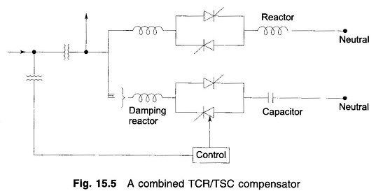
A combined TSC and TCR (Fig. 15.5) is the optimum solution in majority of cases. With this, continuous variable reactive power is obtained throughout the complete control range. Furthermore full control of both inductive and capacitive parts of the compensator is obtained. This is a very advantageous feature permitting optimum performance during large disturbances in the power system (e.g. line faults, load rejection etc) TSC/TCR combinations are characterized by continuous control, no transients, low generations of harmonics, low losses, redundancy, flexible control and operation.
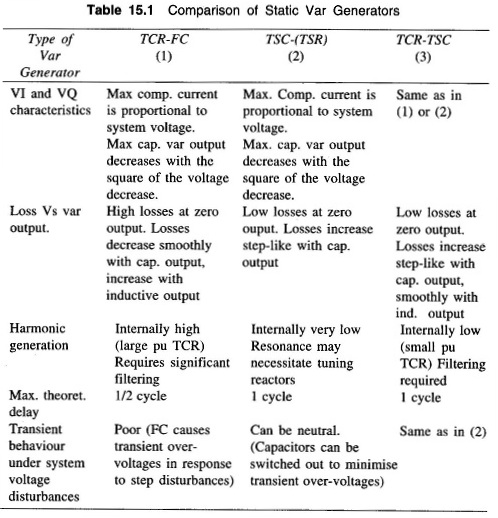
The basic characteristics of the main static var generator schemes are given in Table 15.1.